
cnmm insert
CNMM inserts are a vital component in metal cutting, specifically in turning operations. This guide explores their functionality, selection criteria, applications, and how to optimize their use for enhanced efficiency and precision. We'll delve into the nuances of choosing the right insert grade, chip breaker geometry, and setting proper cutting parameters, all crucial for achieving optimal results. Furthermore, we will cover common issues and troubleshooting tips to ensure successful machining operations. This includes information for selecting tools found and supplied at Wayleading Tools. Remember to consult the official documentation for your specific CNMM insert and machine tools for optimal results.What are CNMM Inserts?A CNMM insert is a standardized type of indexable cutting insert used primarily in turning applications on CNC machines. The 'CNMM' designation refers to the insert's shape, clearance angles, tolerances, and size, following the ISO 1832 standard. Understanding this designation is key to selecting the correct insert for your needs.Decoding the CNMM DesignationThe ISO 1832 standard provides a coded system for designating the characteristics of indexable inserts. For a CNMM insert, each letter provides information:C: Shape (80-degree diamond)N: Clearance angle (0 degrees)M: Tolerance class (specifies dimensional tolerances)M: Insert with a hole and countersink on both sidesFollowing the 'CNMM,' you'll find numbers that define the insert's size (e.g., cutting edge length, thickness) and corner radius. For example, a 'CNMM120408' insert indicates a cutting edge length of 12 mm, a thickness of 4 mm, and a corner radius of 0.8 mm. This can ensure you select the right size for the workpiece and material.Factors to Consider When Choosing a CNMM InsertSelecting the appropriate CNMM insert is critical for achieving optimal machining performance. Several factors must be considered:Material to be MachinedThe material being machined is perhaps the most crucial factor. Different materials require different insert grades to withstand the cutting forces and temperatures involved. Here are some common material groups and recommended insert grades:Steel (P): Choose grades designed for steel, which typically offer high wear resistance and toughness.Stainless Steel (M): Opt for grades with high edge strength and resistance to built-up edge (BUE).Cast Iron (K): Select grades with good wear resistance and the ability to handle interrupted cuts.Aluminum (N): Use grades with sharp cutting edges and polished surfaces to prevent sticking and BUE.Heat Resistant Super Alloys (S): Choose grades with high heat resistance and oxidation resistance.Titanium (H): Select grades with high heat resistance and chemical stability.Insert GradeThe insert grade refers to the material composition and coating of the insert. Common insert materials include cemented carbides, ceramics, cermets, and cubic boron nitride (CBN). Each material offers different properties in terms of hardness, toughness, and wear resistance.Coatings enhance the performance of the insert by providing increased wear resistance, reduced friction, and improved heat resistance. Common coatings include:Titanium Nitride (TiN): General-purpose coating for increased wear resistance.Titanium Carbonitride (TiCN): Higher wear resistance than TiN, suitable for abrasive materials.Aluminum Oxide (Al2O3): Excellent heat resistance, ideal for high-speed cutting.Diamond (CVD/PCD): Extremely hard and wear-resistant, suitable for abrasive non-ferrous materials.Chip Breaker GeometryThe chip breaker geometry is designed to control the formation and flow of chips. Proper chip control is essential for preventing chip entanglement, reducing cutting forces, and improving surface finish. Different chip breaker geometries are available for various applications, such as roughing, finishing, and threading.Consider the following when selecting a chip breaker geometry:Roughing: Choose a geometry with a strong cutting edge and a large chip breaker to handle heavy depths of cut and feed rates.Finishing: Select a geometry with a sharp cutting edge and a small chip breaker to produce a smooth surface finish.General Purpose: Many CNMM inserts can handle both, however performance may be slightly different.Cutting ParametersThe cutting parameters, including cutting speed, feed rate, and depth of cut, significantly impact the performance of the CNMM insert. Optimizing these parameters is essential for achieving the desired results while maximizing tool life.Refer to the insert manufacturer's recommendations for the appropriate cutting parameters for the specific insert grade and material being machined. Factors such as machine tool rigidity, workpiece stability, and coolant application also influence the selection of cutting parameters.Applications of CNMM InsertsCNMM inserts are widely used in various turning applications, including:External Turning: Machining the outer diameter of a cylindrical workpiece.Internal Turning (Boring): Machining the inner diameter of a hole.Facing: Machining the end face of a workpiece.Profiling: Creating complex shapes and contours.Threading: Cutting threads on the outer or inner surface of a workpiece.Their versatility and standardized design make them a popular choice in many machine shops. Finding the right size and material at Wayleading Tools is easy with our quick filtering options.Troubleshooting Common Issues with CNMM InsertsEven with proper selection and application, issues can arise when using CNMM inserts. Here are some common problems and troubleshooting tips:Premature WearPossible Causes: Incorrect insert grade, excessive cutting speed, insufficient coolant, abrasive workpiece material.Troubleshooting: Select a more wear-resistant insert grade, reduce cutting speed, ensure adequate coolant flow, use a coating suitable for abrasive materials.Chipping or FracturePossible Causes: Excessive feed rate, interrupted cuts, unstable workpiece, incorrect insert geometry.Troubleshooting: Reduce feed rate, use a tougher insert grade, improve workpiece stability, choose an insert geometry designed for interrupted cuts.Built-Up Edge (BUE)Possible Causes: Low cutting speed, insufficient coolant, gummy workpiece material.Troubleshooting: Increase cutting speed, ensure adequate coolant flow, use an insert with a polished surface and a sharp cutting edge, select an insert grade with anti-BUE properties.Poor Surface FinishPossible Causes: Excessive feed rate, worn insert, vibration, incorrect cutting parameters.Troubleshooting: Reduce feed rate, replace worn insert, eliminate vibration, optimize cutting parameters.Optimizing CNMM Insert PerformanceTo maximize the performance and lifespan of CNMM inserts, consider the following tips:Use the Correct Toolholder: Ensure that the toolholder is compatible with the insert size and shape.Properly Seat the Insert: Clean the toolholder and insert seat before installing the insert to ensure proper contact.Use the Recommended Torque: Tighten the insert screw to the manufacturer's recommended torque to prevent movement and ensure proper clamping.Inspect Inserts Regularly: Check inserts for wear or damage and replace them as needed.Follow Manufacturer's Recommendations: Adhere to the insert manufacturer's recommendations for cutting parameters and application guidelines.By understanding the factors involved in selecting and using CNMM inserts, machinists can optimize their turning operations for improved efficiency, precision, and tool life. Proper application of these inserts, especially sourced through reliable suppliers such as Wayleading Tools, is paramount to achieving optimal machining outcomes. Remember to always prioritize safety and consult the official documentation for all tools and machinery.
Related products
Related products
Best selling products
Best selling products-
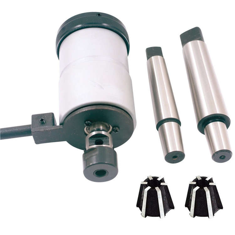 Auto Self Reversible Tapping Chuck In Drill Machine
 -
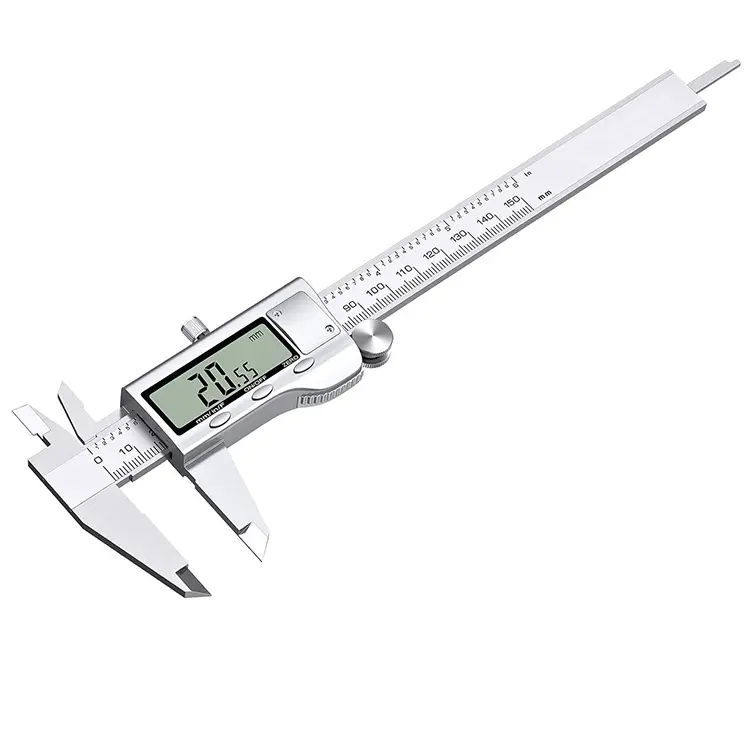
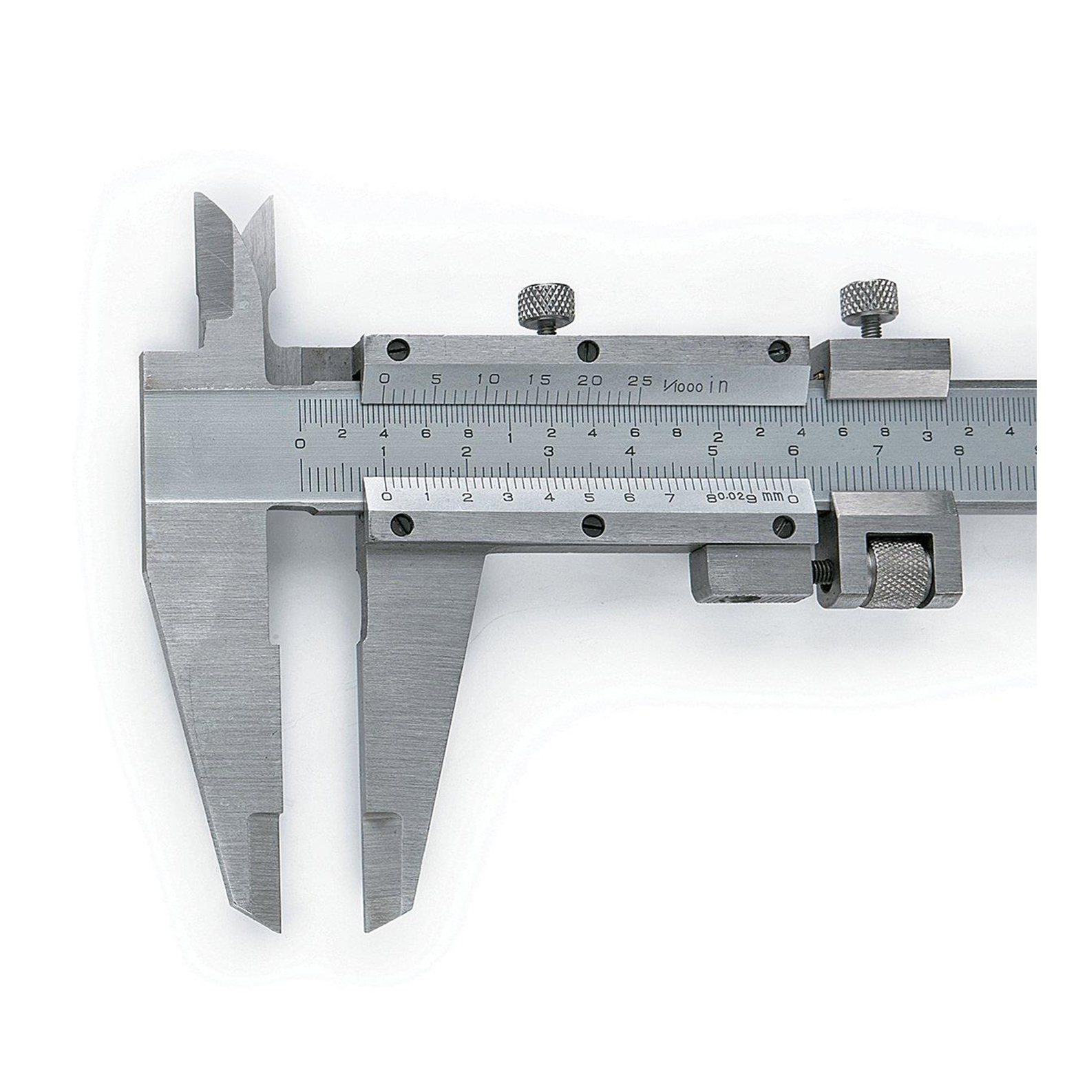 Precision Fine-Adjustment Vernier Caliper Of Metric & Imperial For Industrial
 -
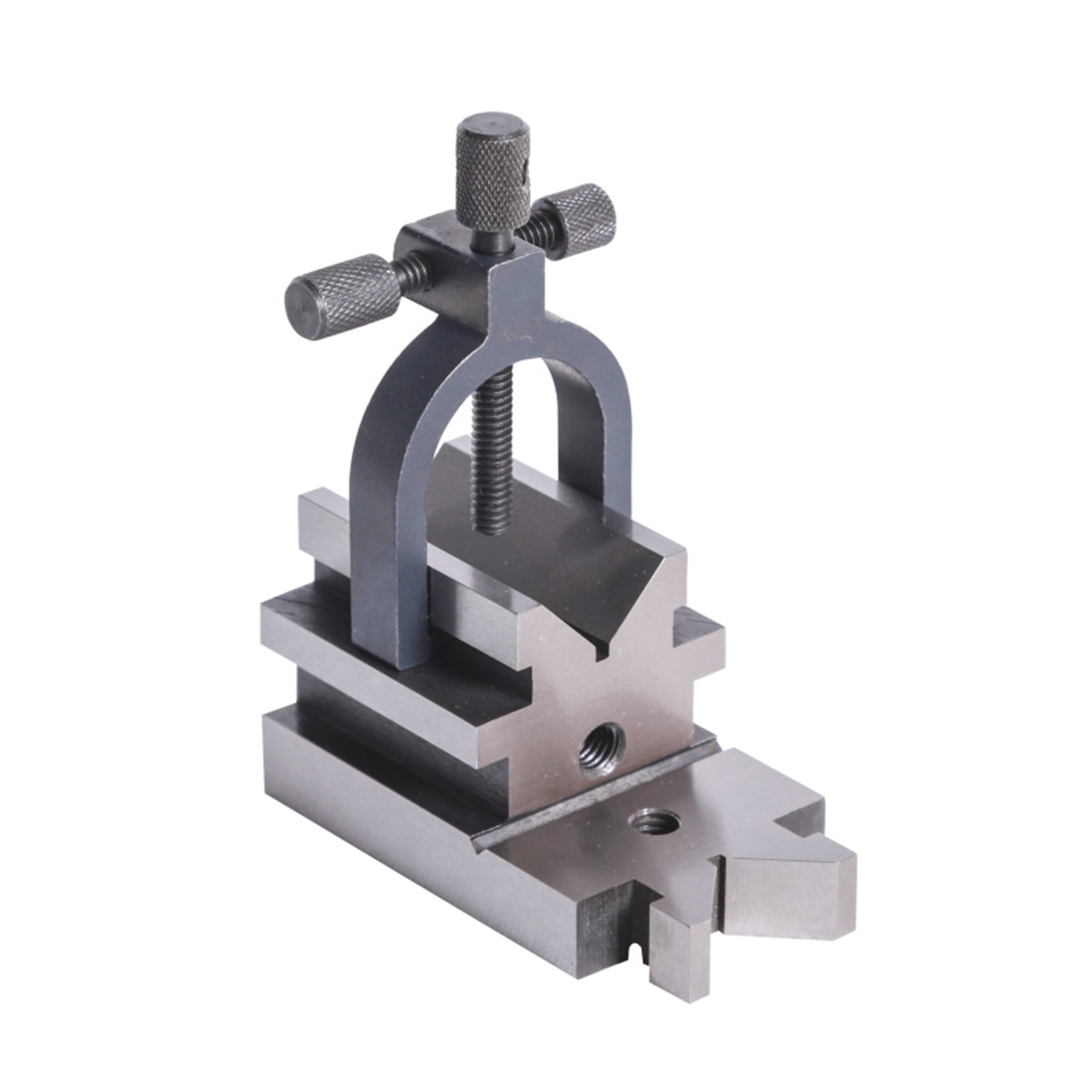
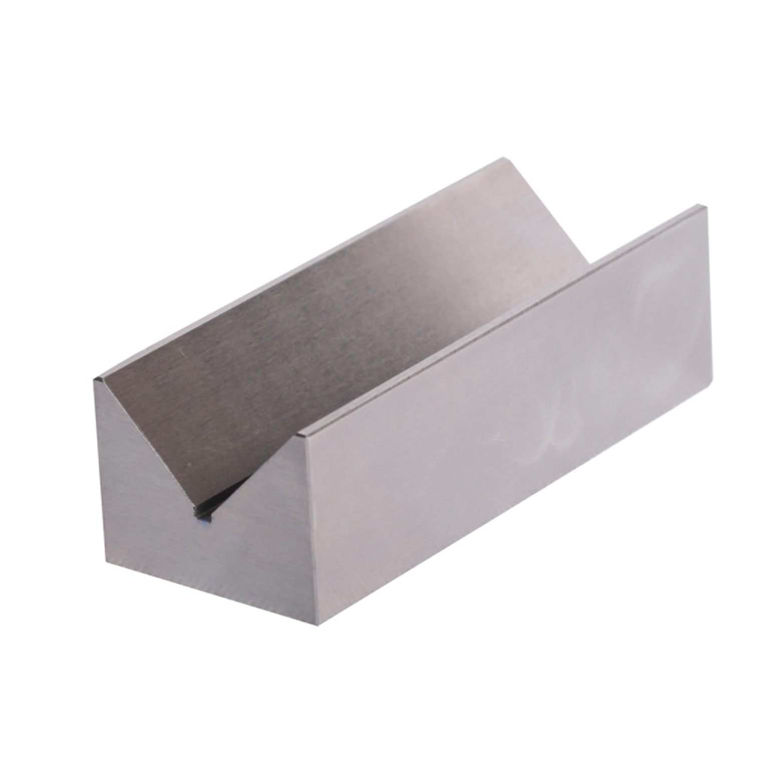 Precision V Block Set With Industrial Type
 -
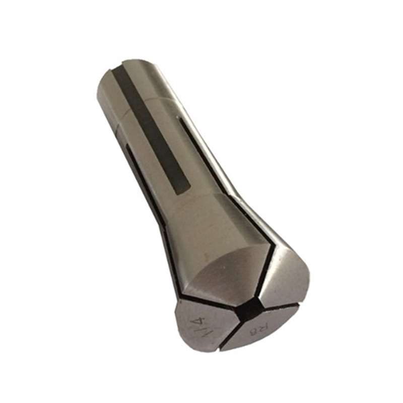
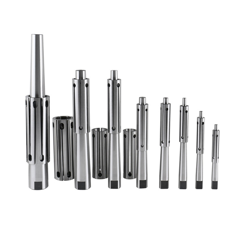 Precision Expanding Mandrel From 9/16″ to 3-3/4″
 -
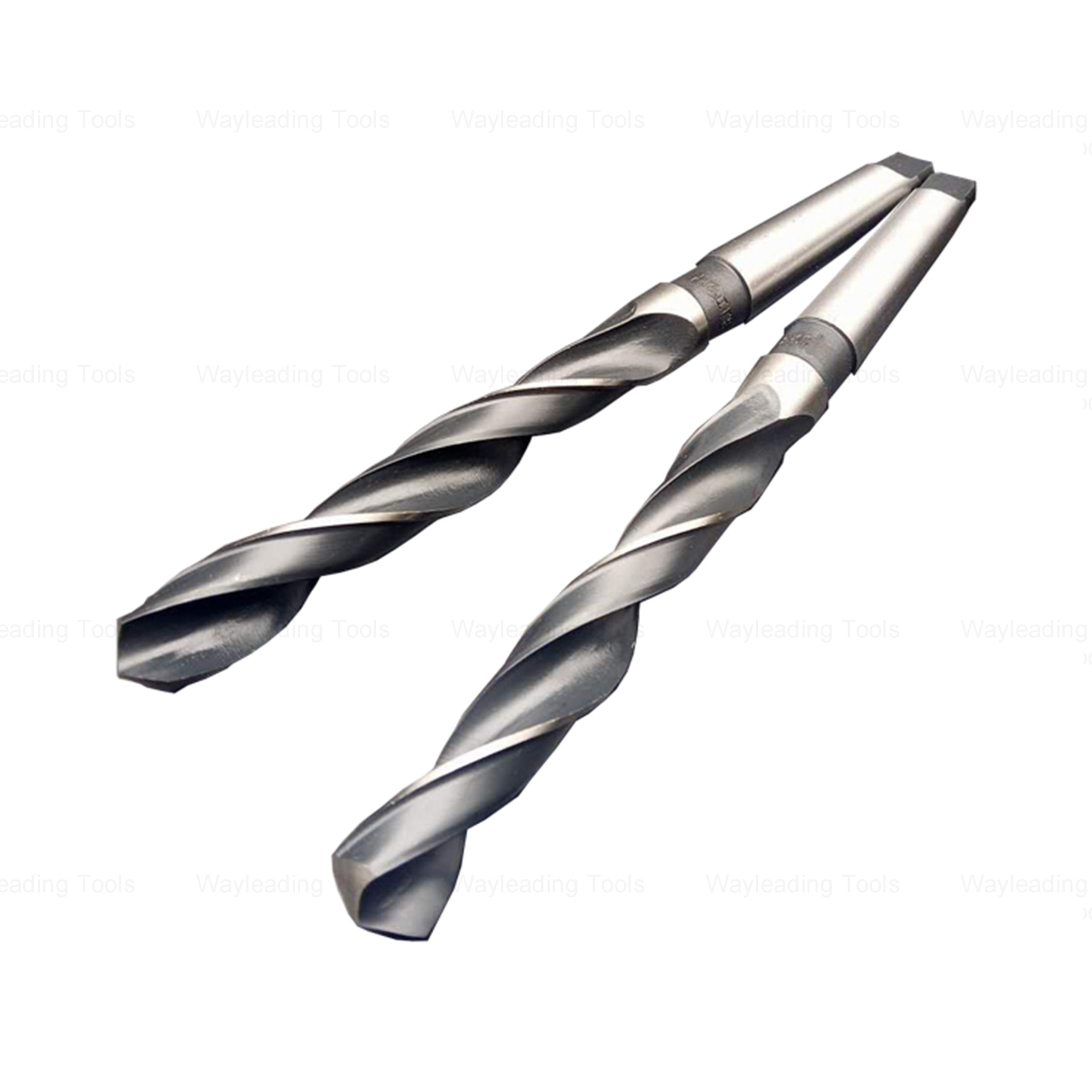
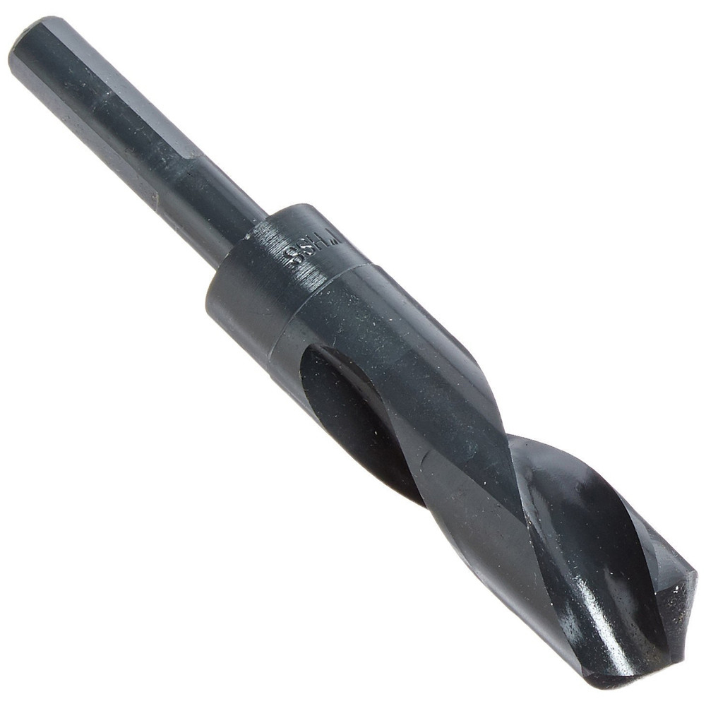 Inch HSS 1/2″ Reduce Shank Drill Bit For Metal Cutting Of High Precision
 -
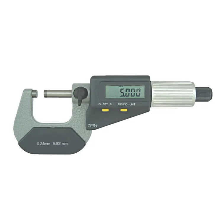 Precision IP54 Digital Outside Micrometer Of Inch & Metric With Data Output
 -
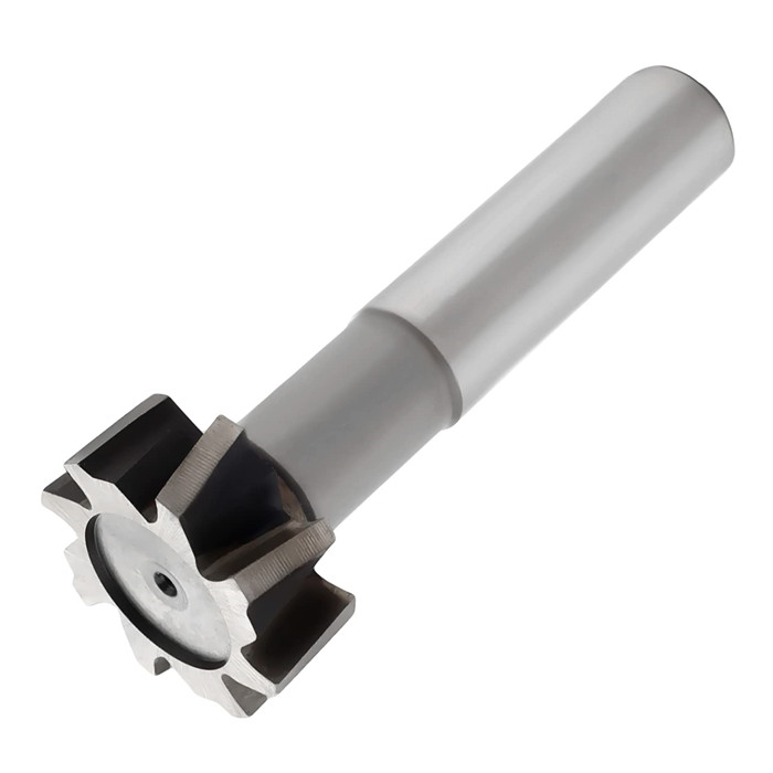 HSS Metric & Inch T Slot End Mill For Industrial
 -
 HSS Inch Convex Milling Cutter For Industrial
 -
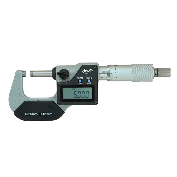 Precision IP65 Digital Outside Micrometer Of Inch & Metric With Data Output
 -
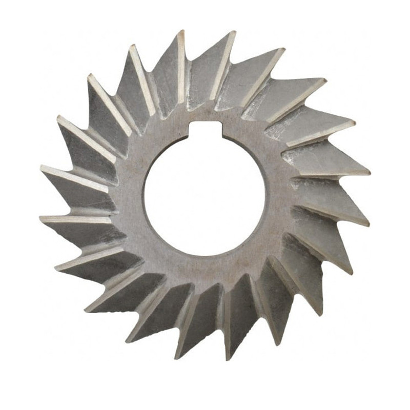 HSS Inch & Metric Single Angle Milling Cutter For Industrial With Bright Or TiN Coated
 -
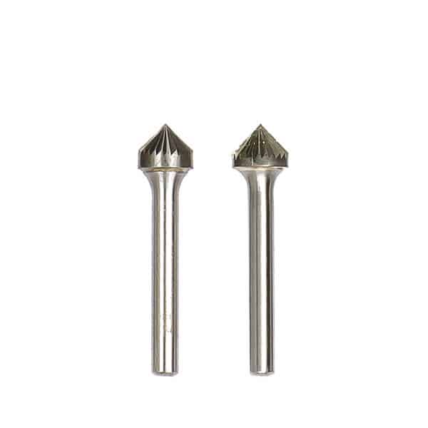
 Type J-60 Degree Cone Tungsten Carbide Rotary Burr
 -
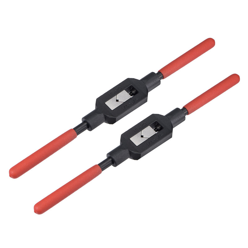 Adjustable Tap And Reamer Wrench For Thread Cutting Tools


