
DCGX insert
DCGX inserts are widely used in metalworking for turning and milling applications, offering excellent chip control and efficient material removal. Understanding their specifications, grades, and optimal usage can significantly improve machining performance and reduce costs. This guide provides a detailed overview of DCGX inserts, covering their geometry, applications, and selection criteria.Understanding DCGX Insert GeometryThe geometry of a DCGX insert plays a crucial role in determining its performance in different machining operations. Key aspects of the geometry include:Shape and Relief AngleDCGX inserts are characterized by their double-sided, positive rake angle design. This geometry reduces cutting forces and heat generation, making them suitable for machining a variety of materials. The 'D' indicates a 55-degree diamond shape. The relief angle, typically 7 degrees, provides clearance between the insert and the workpiece, preventing rubbing and improving surface finish.Chipbreaker DesignThe chipbreaker is a critical feature that controls chip formation and evacuation. Different chipbreaker designs are available for DCGX inserts, each optimized for specific materials and cutting conditions. Common designs include: GM: General-purpose chipbreaker suitable for a wide range of materials. HS: Designed for high-speed machining and finishing applications. LF: Optimized for low feed rates and fine finishing. SF: Designed for stainless steel.DCGX Insert Grades and Material SelectionThe grade of a DCGX insert refers to the material composition and coating. Selecting the appropriate grade is essential for achieving optimal tool life and performance. Popular grades include:Carbide GradesCarbide is the most common material for DCGX inserts, offering a good balance of hardness and toughness. Different carbide grades are available, each with specific properties: P grades: For machining steel and cast iron. M grades: For machining stainless steel and heat-resistant alloys. K grades: For machining cast iron.Coating TechnologiesCoatings enhance the performance of DCGX inserts by increasing wear resistance, reducing friction, and improving heat resistance. Common coatings include: Titanium Nitride (TiN): A general-purpose coating that provides good wear resistance. Titanium Carbonitride (TiCN): Offers higher wear resistance and toughness than TiN. Aluminum Oxide (Al2O3): Provides excellent heat resistance for high-speed machining. Diamond Coating (CVD/PCD): For machining non-ferrous materials such as aluminum, copper, and composites.Applications of DCGX InsertsDCGX inserts are versatile tools suitable for a wide range of turning operations, including:External TurningDCGX inserts are commonly used for external turning of shafts, bars, and other cylindrical components. Their positive rake angle geometry ensures smooth cutting action and excellent surface finish.FacingFacing operations involve machining the end surface of a workpiece to create a flat, smooth surface. DCGX inserts are well-suited for facing due to their ability to provide good chip control and surface finish.ProfilingProfiling involves creating complex shapes and contours on a workpiece. DCGX inserts with appropriate chipbreaker designs can effectively handle profiling operations, delivering accurate and consistent results.Selecting the Right DCGX InsertChoosing the right DCGX insert depends on several factors, including the material being machined, the type of operation, and the desired surface finish. Consider the following guidelines:Material SelectionSelect the appropriate grade based on the material being machined. Use P grades for steel, M grades for stainless steel, and K grades for cast iron.Chipbreaker SelectionChoose a chipbreaker design that is optimized for the specific cutting conditions. GM chipbreakers are suitable for general-purpose applications, while HS chipbreakers are ideal for high-speed machining.Nose RadiusThe nose radius affects the surface finish and cutting forces. A smaller nose radius provides a better surface finish but requires lower feed rates. A larger nose radius allows for higher feed rates but may result in a rougher surface finish. Example DCGX Insert Selection Chart Material Operation Recommended Grade Chipbreaker Example Part Number Steel Roughing P25 GM DCGX11T308-GM P25 Stainless Steel Finishing M15 HS DCGX11T304-HS M15 Cast Iron General Turning K10 GM DCGX11T308-GM K10 Optimizing Cutting ParametersProper cutting parameters are crucial for maximizing the performance and tool life of DCGX inserts. Consider the following guidelines:Cutting SpeedThe cutting speed depends on the material being machined and the insert grade. Consult the manufacturer's recommendations for the optimal cutting speed range.Feed RateThe feed rate affects the surface finish and chip control. A lower feed rate provides a better surface finish but may result in longer machining times. A higher feed rate allows for faster machining but may lead to a rougher surface finish.Depth of CutThe depth of cut should be adjusted based on the material being machined and the insert's capabilities. A smaller depth of cut reduces cutting forces and heat generation, while a larger depth of cut allows for faster material removal.ConclusionDCGX inserts are versatile and efficient cutting tools that can significantly improve machining performance. By understanding their geometry, grades, and applications, you can select the right insert for your specific needs and optimize cutting parameters for maximum productivity. At Wayleading Tools, we offer a wide range of high-quality DCGX inserts to meet your machining requirements. Contact us today to learn more about our products and services.Disclaimer: The information provided in this guide is for general informational purposes only and does not constitute professional advice. Always consult with a qualified expert before making any decisions related to machining operations. While the example part numbers are representative, always verify compatibility and specifications with your tooling supplier before purchase.
Related products
Related products

Best selling products
Best selling products-
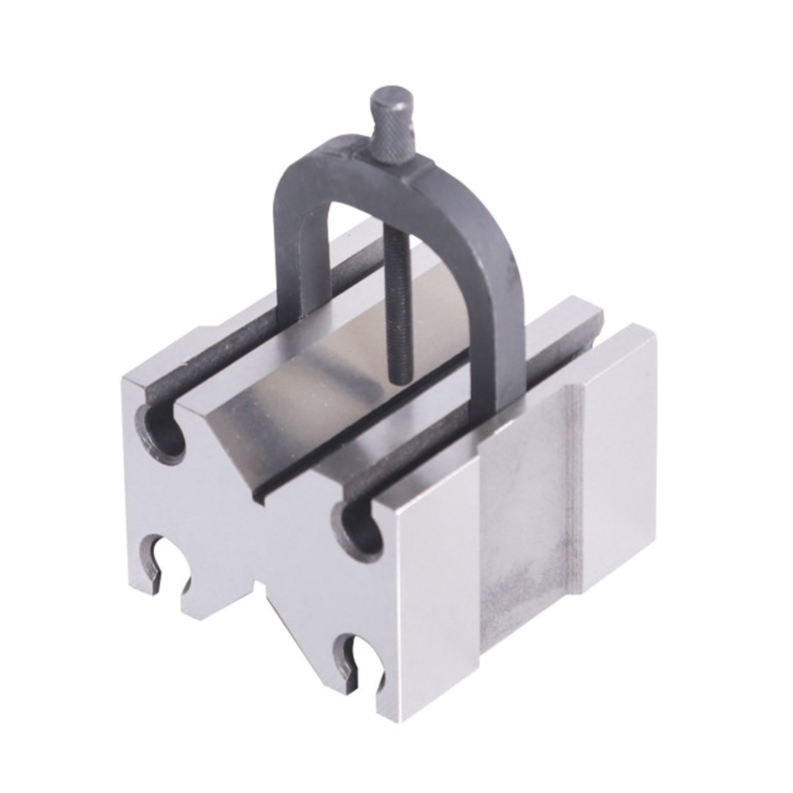
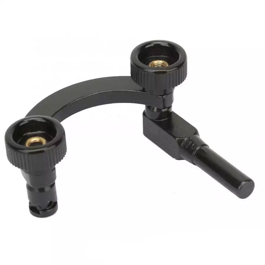 Precision Dial Test Indicator Holder For Industrial
 -
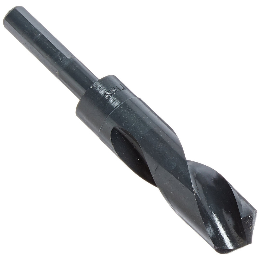 Inch HSS 1/2″ Reduce Shank Drill Bit For Metal Cutting Of High Precision
 -
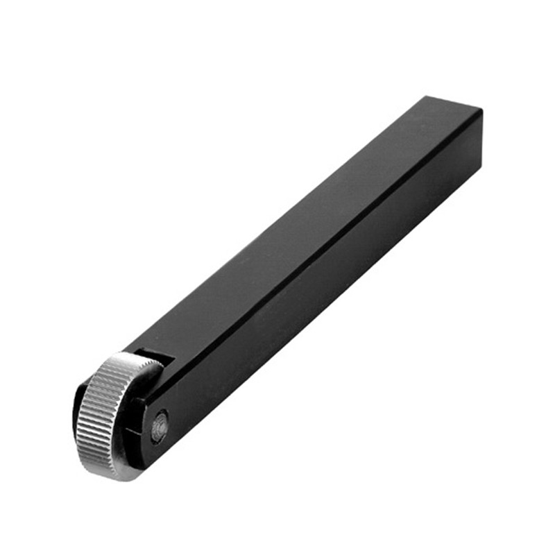 Single Wheel Knurling Tools With Straight Pattern For Industrial Type
 -
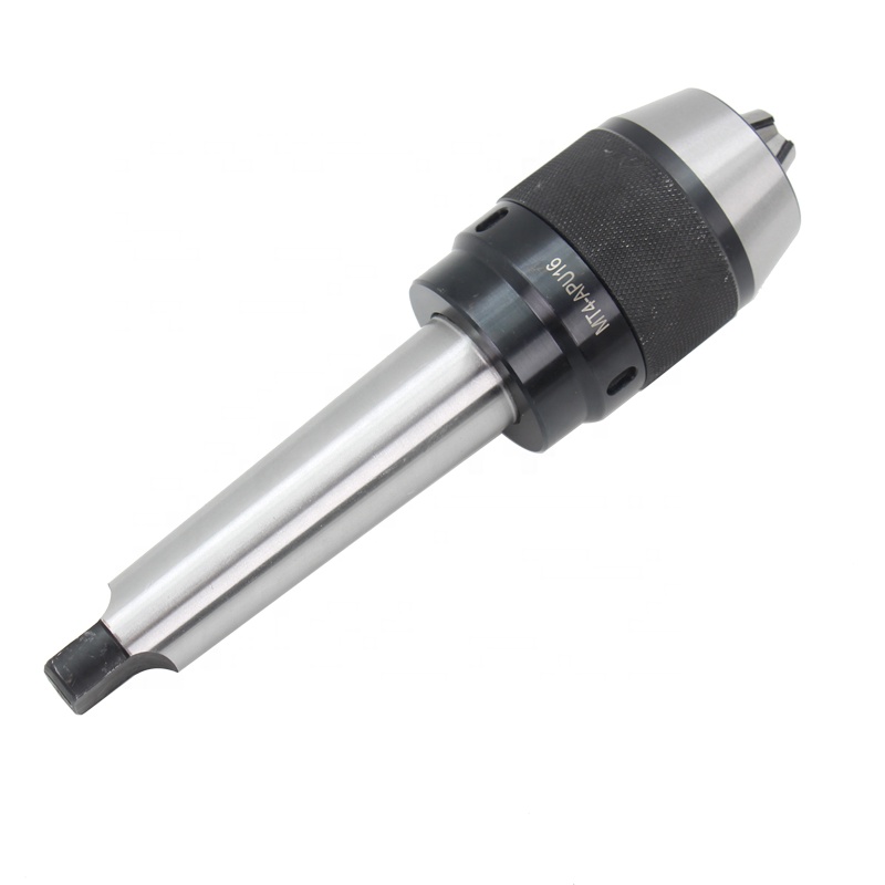 MT-APU Drill Chuck Holder With Keyless Type
 -
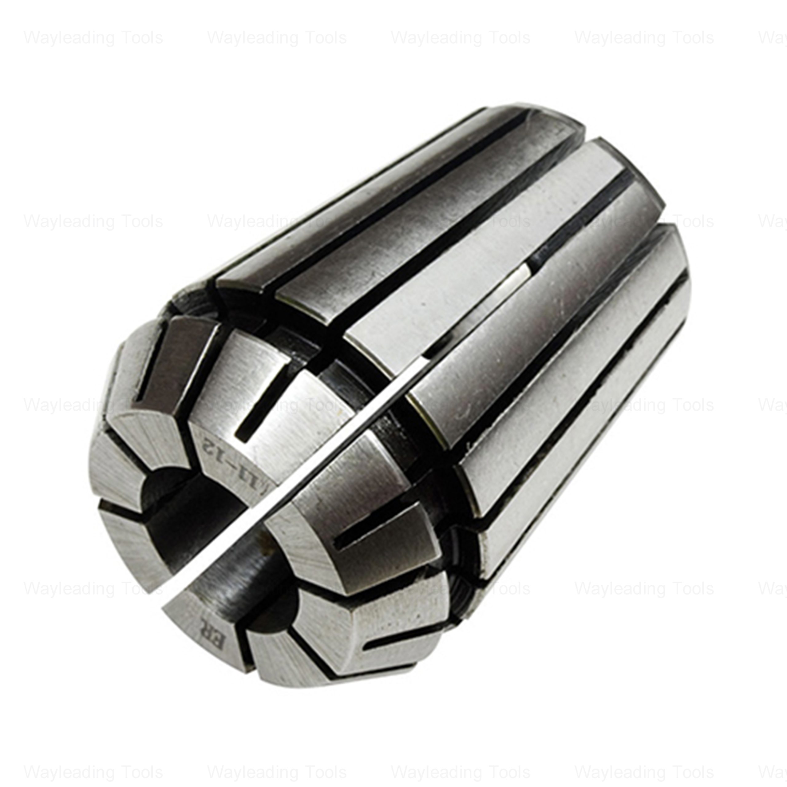 Metric ER Collets – High Precision, for Milling Applications
 -
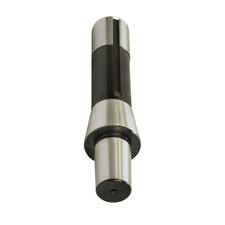 R8 Drill Chuck Arbor For Milling Machine
 -
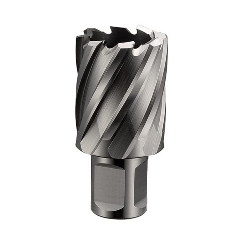 Metric HSS Annular Cutters With Weldon Shank For Metal Cutting
 -
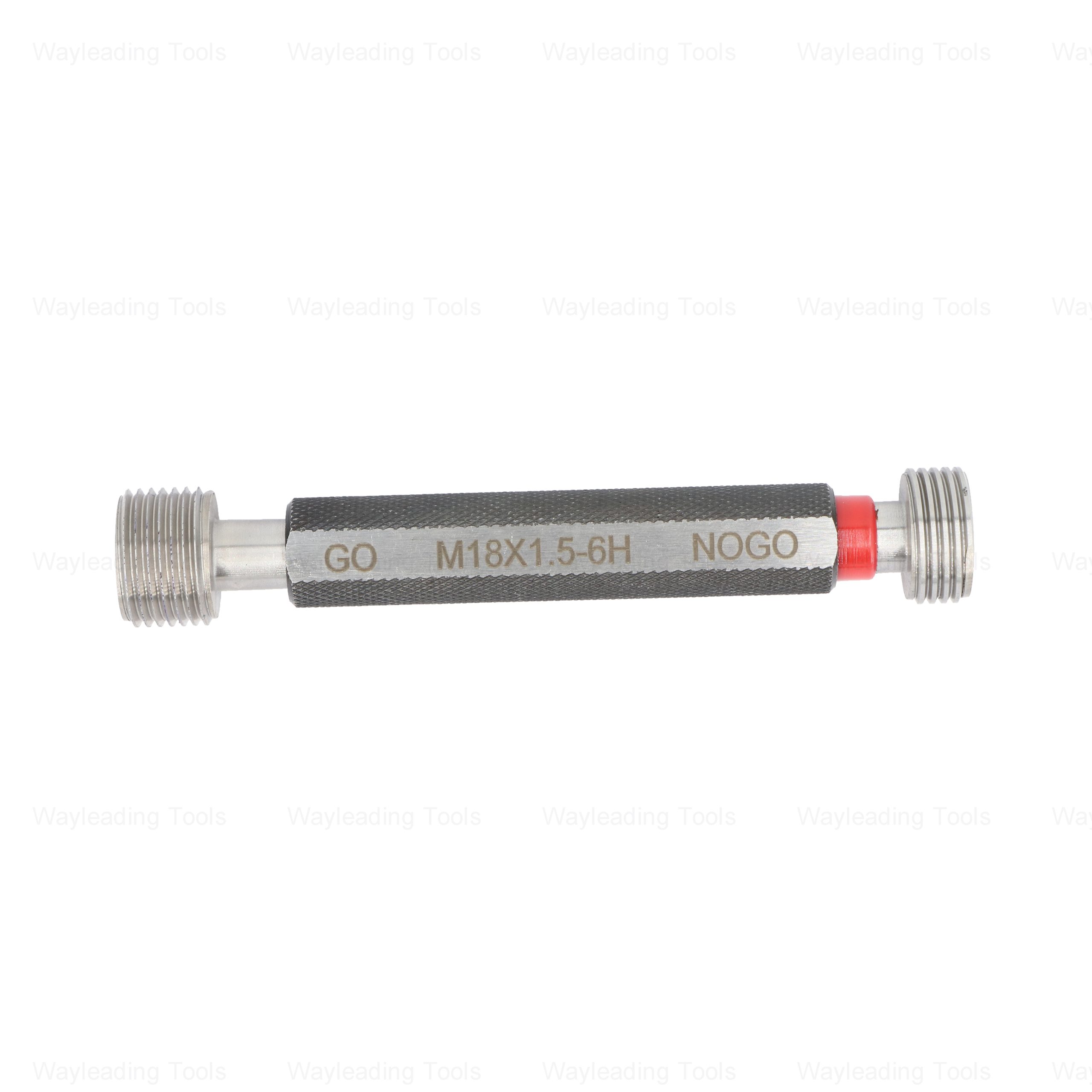 High-Precision Metric Thread Plug Gauge – 6H Class, GO & NO-GO Ends
 -
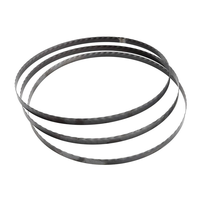 M42 Bi-Metal Bandsaw Blades For Industrial Type
 -
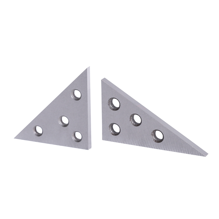 Precision 2pcs Angle Blocks Set With High Quality Type
 -
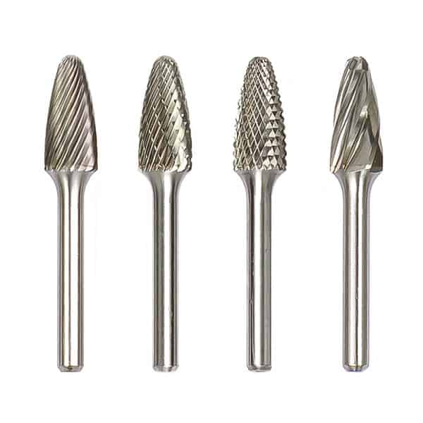
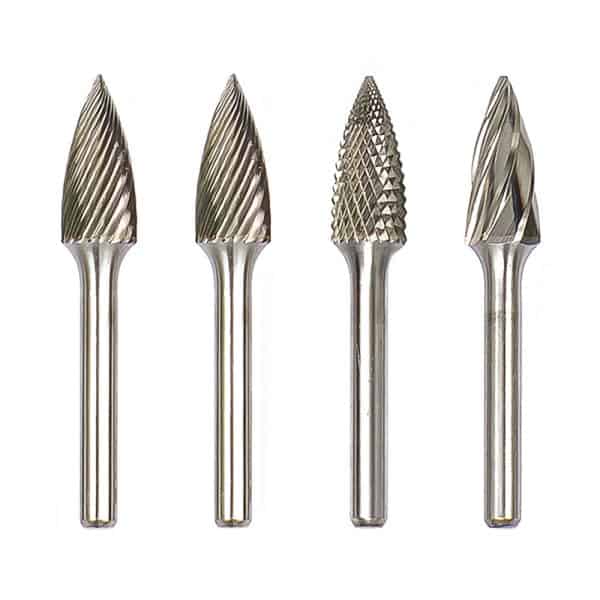 Type G Arc Pointed Tree Tungsten Carbide Rotary Burr
 -
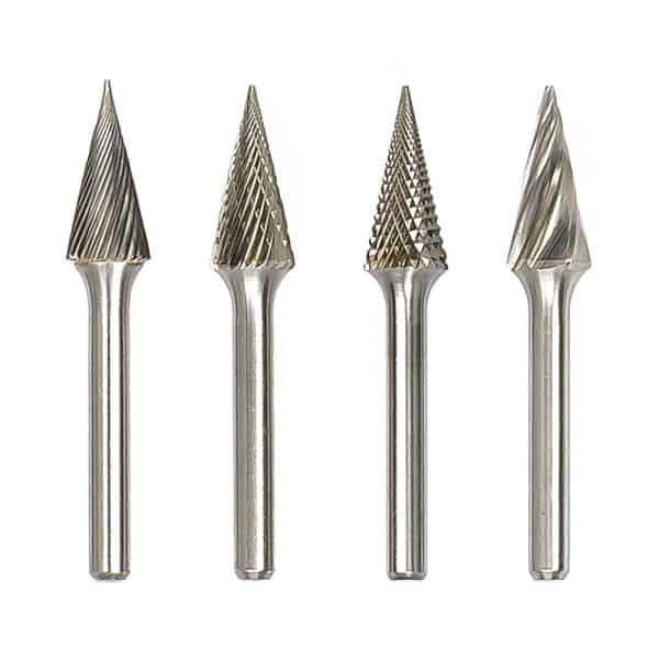 Type M Cone Tungsten Carbide Rotary Burr
Related search
Related search- PSRN turning tool holder Supplier
- Wholesale partial profile 60 degree threading insert
- Wholesale MSKN boring bar
- SDUC boring bar Manufacturers
- calipers with long jaws Factories
- High-Quality ER Collet set
- sneu insert Manufacturer
- SDNC turning tool holder Manufacturer
- Wholesale dnmg insert
- Wholesale boring tool


