
dnmg insert
DNMG inserts are double-sided negative inserts used in metal turning operations. They are known for their durability and ability to handle a wide range of materials. This guide provides a detailed overview of DNMG inserts, covering their geometry, applications, material grades, and selection criteria, helping you choose the right insert for your specific machining needs.Understanding DNMG Insert GeometryThe DNMG insert gets its name from its standardized designation, which describes its shape and characteristics. Let's break down what each letter and number in the designation represents: D: Diamond shape (55-degree included angle) N: Clearance angle of 0 degrees (no relief) M: Tolerance class (standard tolerance) G: Chip breaker geometryUnderstanding this designation helps you quickly identify the insert's basic properties. However, within the DNMG insert category, there are variations in size, nose radius, and chip breaker geometry, each designed for specific applications.Key Applications of DNMG InsertsDNMG inserts are versatile tools suitable for a range of turning operations. Here are some of their common applications: General Turning: They are effective for general-purpose turning of steel, stainless steel, and cast iron. Roughing Operations: Due to their robust design, they can withstand the heavy cutting forces involved in roughing. Interrupted Cuts: Their toughness makes them suitable for machining parts with interrupted cuts (e.g., castings with sand inclusions). Finishing Operations: With appropriate chip breaker geometry and nose radius, DNMG inserts can also be used for finishing.Choosing the Right Material Grade for Your DNMG InsertThe material grade of a DNMG insert significantly impacts its performance and tool life. Here's a breakdown of common material grades and their applications: Carbide: General-purpose grade suitable for a wide range of materials and cutting conditions. Cermet: Offers excellent wear resistance and is ideal for finishing operations at high cutting speeds. Coated Carbide: Provides enhanced wear resistance and toughness compared to uncoated carbide. Coatings like TiN (Titanium Nitride), TiCN (Titanium Carbonitride), and Al2O3 (Aluminum Oxide) improve performance in specific applications. Cubic Boron Nitride (CBN): Extremely hard material suitable for machining hardened steels and cast irons. Diamond (PCD): Ideal for machining non-ferrous materials such as aluminum, copper, and plastics.Selecting the Optimal Chip Breaker GeometryChip breaker geometry plays a critical role in chip control and overall machining performance. DNMG inserts come with various chip breaker designs, each tailored for specific cutting conditions: Roughing Chip Breakers: Designed to break chips into small, manageable pieces during heavy roughing operations. Medium Chip Breakers: Suitable for a wide range of cutting conditions, providing a good balance between chip control and cutting forces. Finishing Chip Breakers: Designed to produce small, consistent chips for optimal surface finish.Always consult the manufacturer's recommendations for the specific chip breaker geometry best suited for your application. For example, Wayleading Tools, a leading provider of cutting tools, provides detailed technical specifications and application guidelines for their range of DNMG inserts. You can find more information on their website at www.wayleading.com.DNMG Insert Size and Nose Radius ConsiderationsThe size and nose radius of the DNMG insert are important factors to consider. Common sizes are DNMG 150404, DNMG 150608, and DNMG 150408, with the numbers indicating the insert's dimensions in millimeters (e.g., cutting edge length and thickness). The nose radius affects surface finish and cutting forces. A smaller nose radius provides a better surface finish but may be more prone to vibration. A larger nose radius is more robust but may generate higher cutting forces.Troubleshooting Common Issues with DNMG InsertsEven with the right DNMG insert, problems can arise during machining. Here are some common issues and their potential solutions: Excessive Wear: Check cutting parameters (speed, feed, depth of cut). Ensure adequate coolant supply. Select a more wear-resistant grade. Chipping: Reduce cutting speed and feed. Choose a tougher grade. Inspect the machine for vibration. Built-Up Edge (BUE): Increase cutting speed. Use a sharper cutting edge. Apply a cutting fluid designed to prevent BUE. Vibration: Reduce cutting speed and feed. Ensure the workpiece and machine are rigidly supported. Select an insert with a smaller nose radius.DNMG Insert Cutting Parameter GuidelinesThe following table provides a general guideline for cutting parameters when using DNMG inserts. Always refer to the manufacturer's recommendations for specific materials and cutting conditions. Material Cutting Speed (m/min) Feed Rate (mm/rev) Depth of Cut (mm) Steel (Low Carbon) .2-0.4 1-3 Steel (Alloy) .15-0.3 1-2 Stainless Steel .1-0.25 0.5-1.5 Cast Iron .25-0.45 1.5-3 Note: These are approximate values and should be adjusted based on specific cutting conditions and machine capabilities.ConclusionDNMG inserts are a popular choice for metal turning due to their versatility and durability. By understanding their geometry, material grades, chip breaker designs, and application guidelines, you can optimize your machining operations and achieve the desired results. Always consult with cutting tool experts, such as those at Wayleading Tools, to select the perfect DNMG insert for your specific needs. Don’t hesitate to contact Wayleading Tools for a comprehensive selection of high-quality cutting tools to enhance your machining processes.Disclaimer: The information provided in this article is for general guidance only. Always refer to the manufacturer's specifications and safety guidelines before using any cutting tools.References:Wayleading Tools: www.wayleading.com
Related products
Related products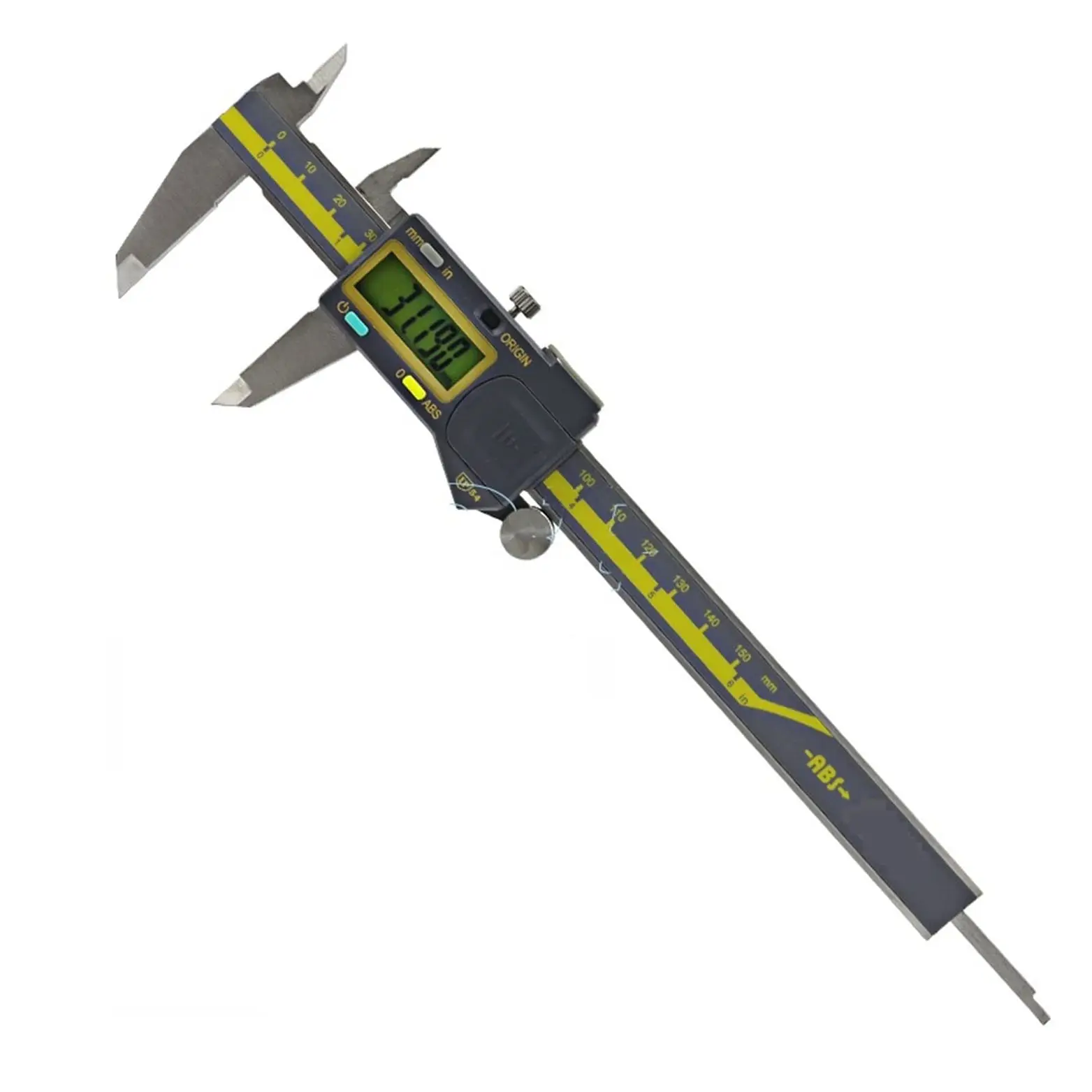
Best selling products
Best selling products-
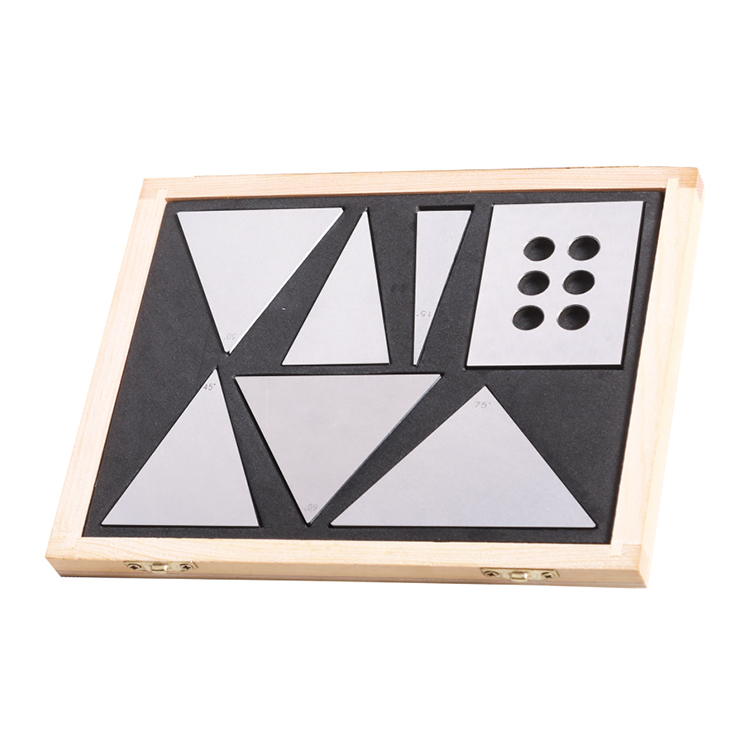 Precision 7pcs Angle Blocks Set With High Quality Type
 -
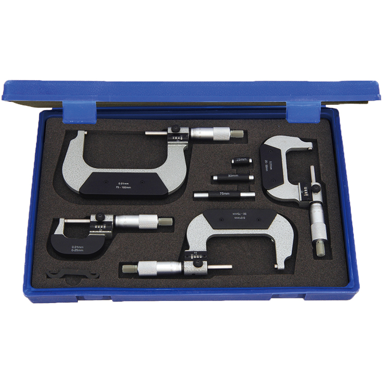
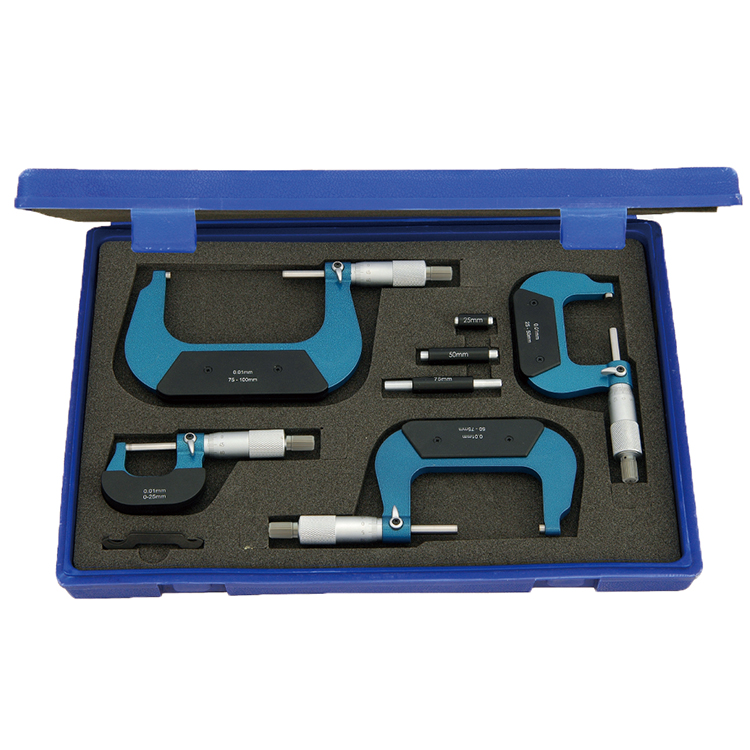 Outside Micrometer Set Of Inch & Metric For Industrial
 -
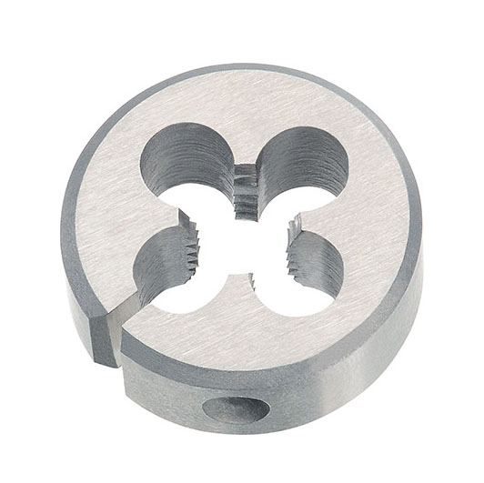 HSS ISO Metric Round Die Wieh Splite Or Adjustable Splite Type
 -
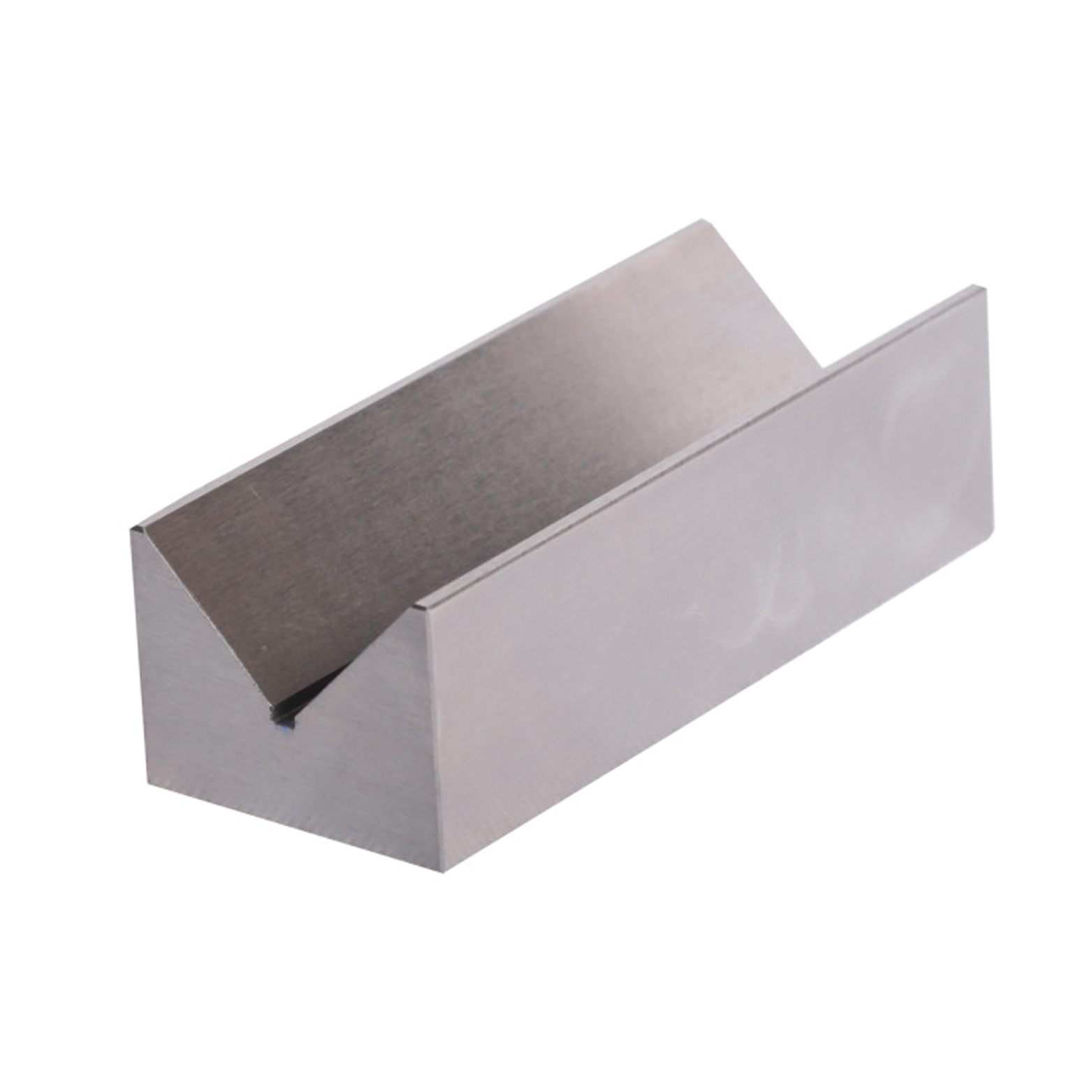 Precision V Block Set With Industrial Type
 -
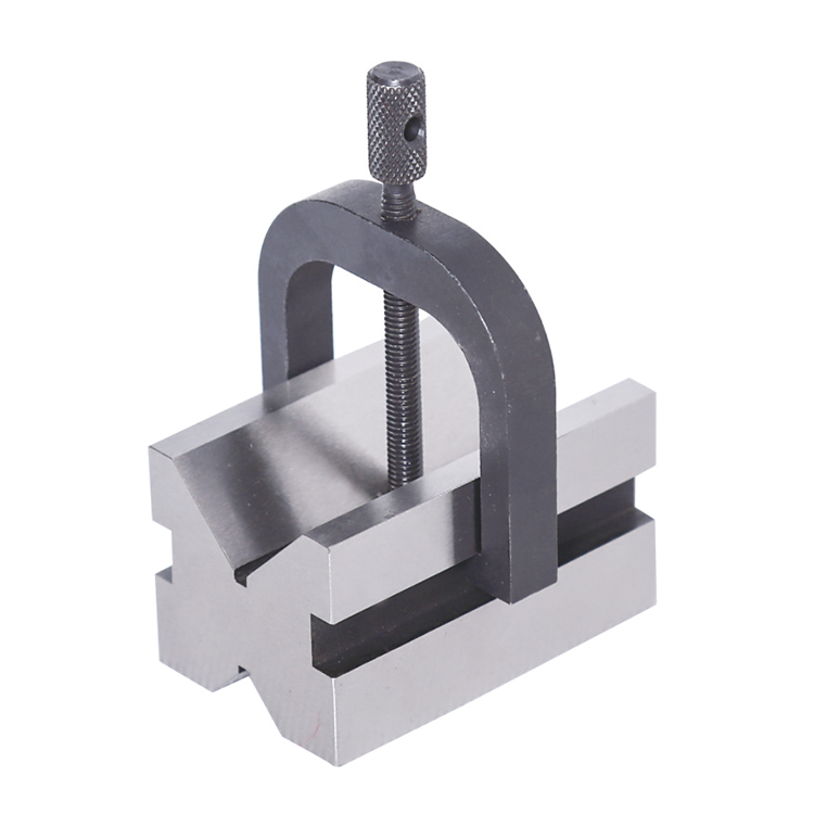 Precision V Block And Clamps Set With High Quality Type
 -
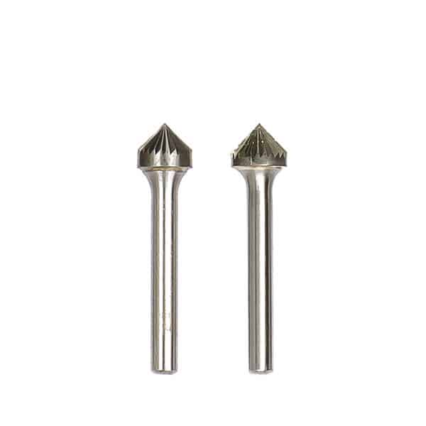 Type K-90 Degree Cone Tungsten Carbide Rotary Burr
 -
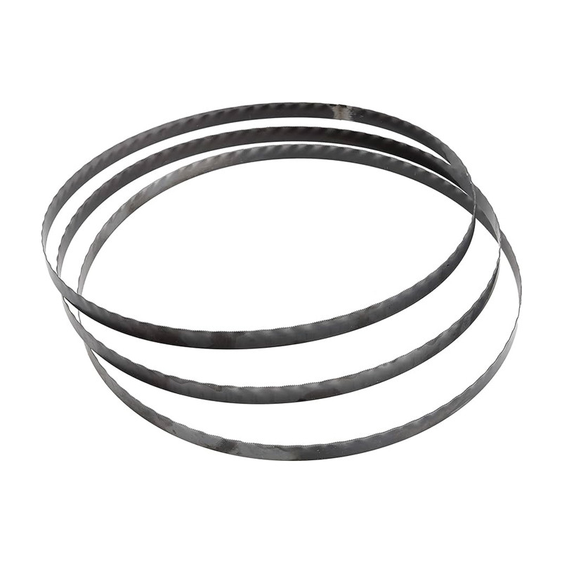 M42 Bi-Metal Bandsaw Blades For Industrial Type
 -
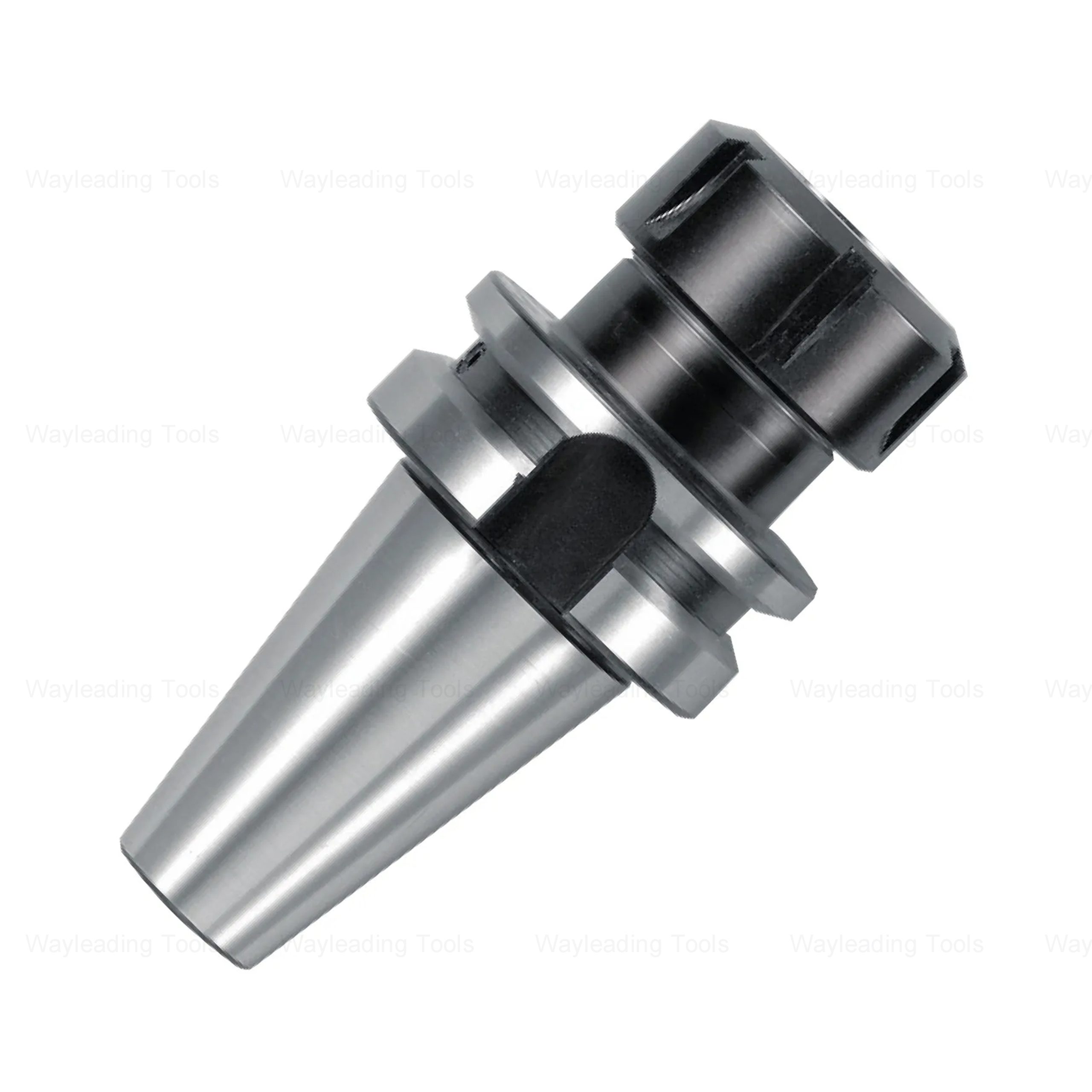 High Precision BT-ER Collet Chuck – CNC Tool Holder, Spring Type, ER16–ER40
 -
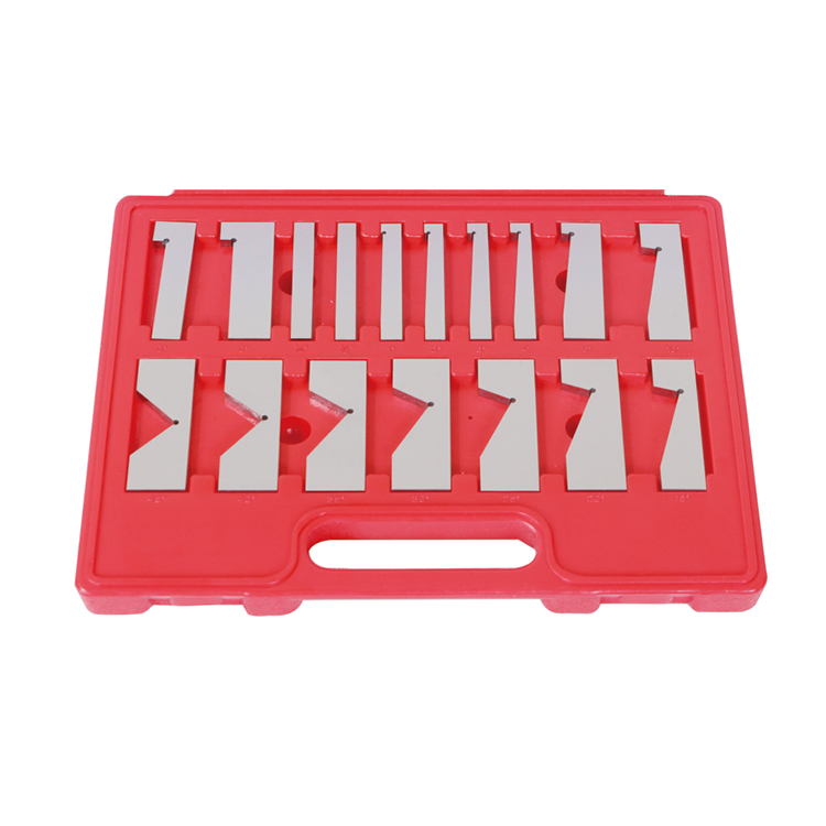 Precision 17pcs Angle Blocks Set With High Quality Type
 -
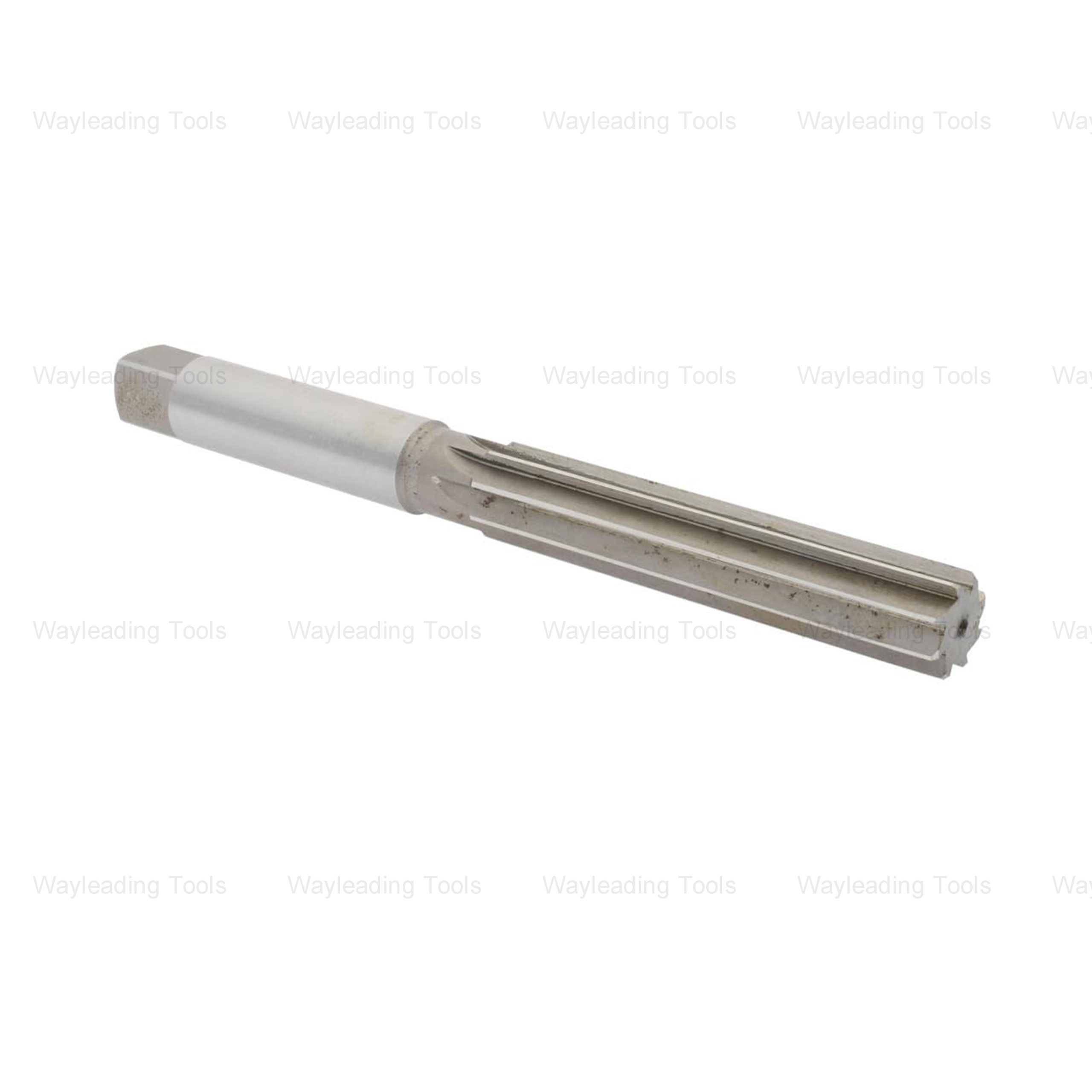 HSS Hand Reamers – Metric & Inch Sizes, Straight or Spiral Flutes
 -
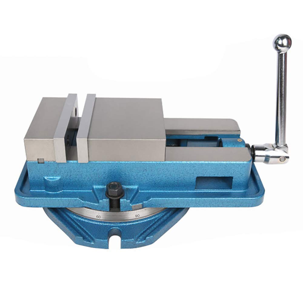 QM ACCU-Lock Precision Machine Vises With Swivel Base
 -
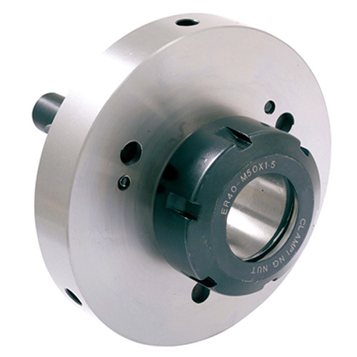 Camlock ER Collet Fixture With Lathe Collet Chuck
Related search
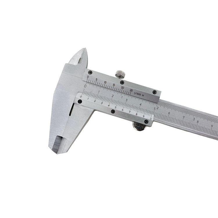
Related search- micrometer caliper Factories
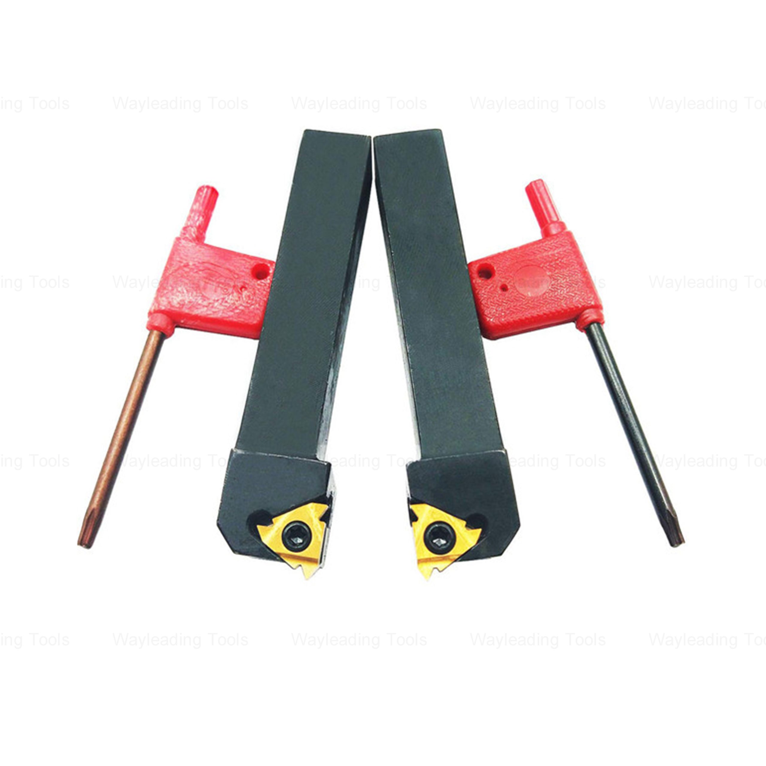
- thread cutting tool Suppliers
- thread pitch gauges
- face milling cutter holder Supplier
- Round Die Factories
- High-Quality SE indexable thread turning tool
- R8 Drill Chuck Arbor
- speedy drill with quick release carbide cutting head Factories
- british standard taper pipe full profile threading insert Suppliers
- turning tool set Manufacturer


