
High-Quality CCGX insert
High-Quality CCGX inserts are essential components in a variety of metalworking applications, especially for machining stainless steel and other challenging materials. They are known for their excellent wear resistance, high cutting speeds, and superior surface finishes. Understanding the key features, selection criteria, and optimal usage of these inserts is crucial for achieving efficient and precise machining operations.
Understanding CCGX Inserts
What are CCGX Inserts?
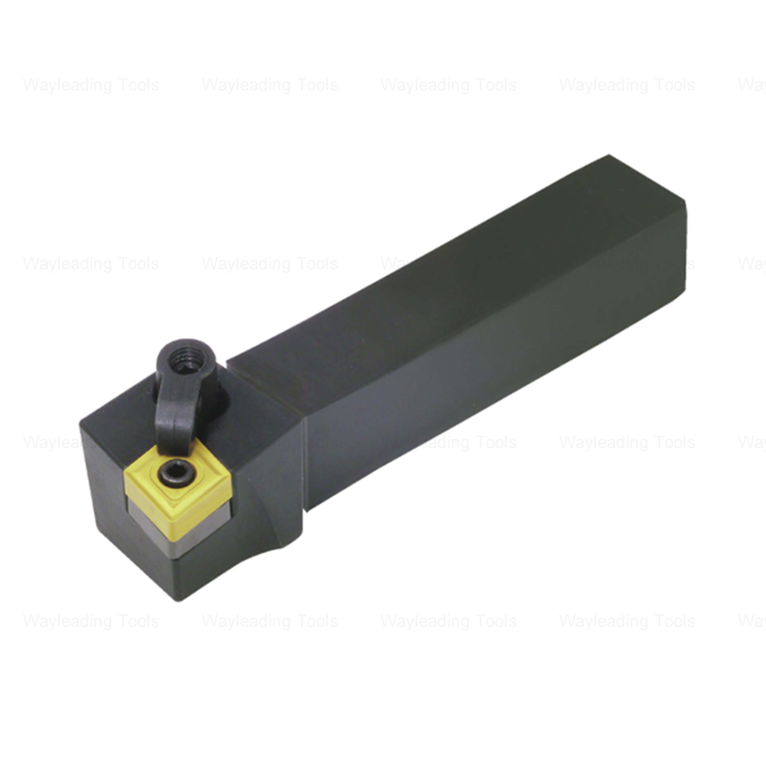
CCGX inserts are a specific type of indexable cutting tool insert used primarily for turning and boring operations. The 'CC' designates the insert's shape (80° diamond), 'G' represents the relief angle, and 'X' signifies the presence of a chipbreaker. The 'High-Quality CCGX insert' is designed to deliver precise cutting performance and extended tool life when machining various materials.
Key Features of High-Quality CCGX Inserts
Choosing a high-quality CCGX insert depends on its key features:
- Material: The insert substrate is the base material and is generally made of cemented carbide. The grade and the grain size will have an impact on the toughness and wear resistance.
- Coating: Coatings, such as TiN (Titanium Nitride), TiCN (Titanium Carbonitride), and AlTiN (Aluminum Titanium Nitride), enhance wear resistance, heat resistance, and reduce friction. The correct choice depends on the material you are machining.
- Chipbreaker Design: The chipbreaker is designed to control chip formation, preventing long, stringy chips that can interfere with the cutting process and damage the workpiece.
- Tolerance: Closer tolerance control will lead to better performance.
- Edge Preparation: Honing or micro-rounding of the cutting edge strengthens the insert and improves tool life.
Selecting the Right CCGX Insert
Material Compatibility
The material you're machining is the primary factor in selecting a high-quality CCGX insert. Consider the following:
- Steel: For general-purpose steel machining, inserts with a PVD coating like TiN or TiCN are often suitable.
- Stainless Steel: Stainless steel requires inserts with high heat resistance and toughness. AlTiN coatings and sharper cutting edges are beneficial.
- Cast Iron: Inserts for cast iron should have good wear resistance. A CVD coated insert is recommended.
- Aluminum: Use uncoated inserts with polished surfaces and sharp cutting edges to prevent built-up edge (BUE).
- Heat-Resistant Alloys (HRSA): Inserts for HRSA require extreme heat resistance and toughness. Consider ceramic or CBN (Cubic Boron Nitride) inserts for high-performance machining.
Insert Grade Selection
Insert grades are typically classified based on ISO designations (e.g., P, M, K). These grades indicate the insert's suitability for different material groups. For example:
- P-Grade: Suitable for machining steel.
- M-Grade: Suitable for machining stainless steel.
- K-Grade: Suitable for machining cast iron.
Refer to the insert manufacturer's catalog for specific grade recommendations based on the material and application.
Geometry and Chipbreaker Considerations
The insert geometry and chipbreaker design play a crucial role in chip control and cutting performance. Choose a chipbreaker that effectively breaks the chips into manageable sizes. A good chipbreaker will improve tool life and surface finish.
Applications of High-Quality CCGX Inserts
High-Quality CCGX inserts are widely used in various metalworking applications, including:
- Turning: External and internal turning of cylindrical parts.
- Boring: Enlarging existing holes or creating new holes.
- Facing: Machining flat surfaces on the ends of workpieces.
- Profiling: Creating complex shapes and contours.
Optimizing Performance with CCGX Inserts
Cutting Parameters
Proper cutting parameters are essential for maximizing the performance of high-quality CCGX inserts. Consider the following:
- Cutting Speed (Vc): Adjust the cutting speed based on the material, insert grade, and coating. Refer to the insert manufacturer's recommendations.
- Feed Rate (f): The feed rate determines the material removal rate and surface finish. Higher feed rates result in faster machining but can also increase tool wear.
- Depth of Cut (ap): The depth of cut influences the cutting forces and chip formation. Use a depth of cut that is appropriate for the insert and workpiece material.
Coolant Application
Using coolant can significantly improve the performance of high-quality CCGX inserts. Coolant helps to:
- Reduce heat buildup at the cutting edge.
- Flush away chips.
- Improve surface finish.
Apply coolant directly to the cutting zone for maximum effectiveness.
Toolholding
A rigid and accurate toolholder is crucial for achieving optimal results. Ensure that the insert is properly secured in the toolholder and that the toolholder is mounted securely in the machine. This reduces vibration and improves machining accuracy.
Troubleshooting Common Issues
Premature Wear
Premature wear can be caused by:
- Incorrect cutting parameters.
- Using the wrong insert grade for the material.
- Insufficient coolant.
- Excessive vibration.
Adjust the cutting parameters, select the appropriate insert grade, ensure adequate coolant flow, and address any vibration issues.
Chip Control Problems
Poor chip control can be caused by:
- Incorrect chipbreaker design.
- Inadequate feed rate.
- Dull cutting edge.
Select a chipbreaker that is appropriate for the material and cutting conditions. Increase the feed rate to promote chip breaking and replace dull inserts.
Wayleading Tools: Your Partner for High-Quality Cutting Tools
At Wayleading Tools, we offer a wide range of high-quality CCGX inserts designed to meet the needs of various metalworking applications. Our inserts are manufactured using the latest technology and highest quality materials, ensuring exceptional performance and long tool life. Contact us today to learn more about our products and how we can help you optimize your machining operations.
Examples of CCGX insert parameters
| Insert Parameter | Description | Typical Range/Value |
|---|---|---|
| Cutting Speed (Vc) | The speed at which the cutting edge moves relative to the workpiece. | 50-200 m/min (Steel), 80-300 m/min (Aluminum) |
| Feed Rate (f) | The distance the insert advances per revolution of the workpiece. | 0.1-0.4 mm/rev (Roughing), 0.05-0.2 mm/rev (Finishing) |
| Depth of Cut (ap) | The depth of material removed in a single pass. | 0.5-5 mm (Roughing), 0.1-1 mm (Finishing) |
| Nose Radius (r) | The radius of the cutting edge. | 0.4 mm, 0.8 mm, 1.2 mm |
Data parameters are for reference only, please use according to the actual situation. For specific parameters, please refer to the official product specifications.
Related products
Related products
Best selling products
Best selling products-
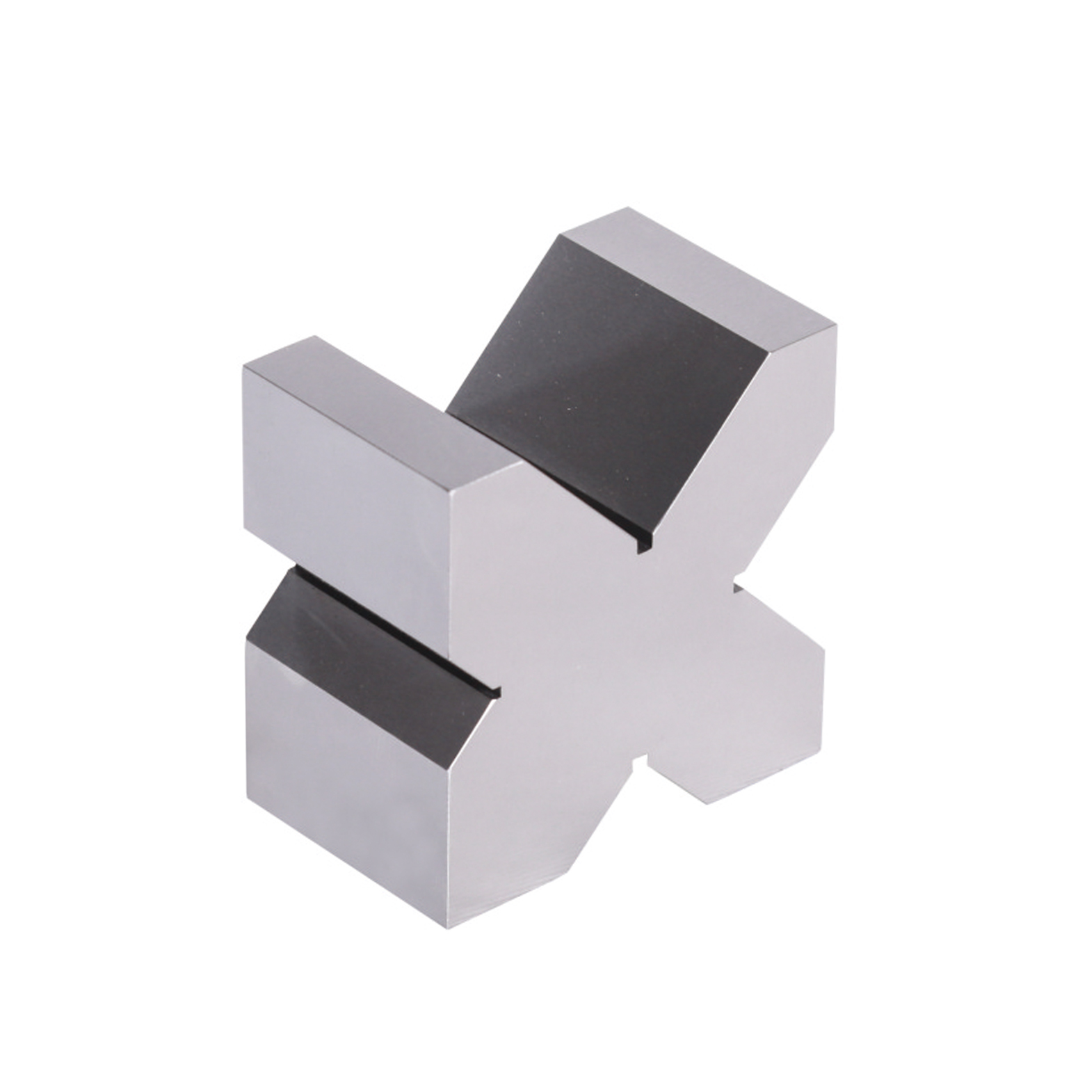
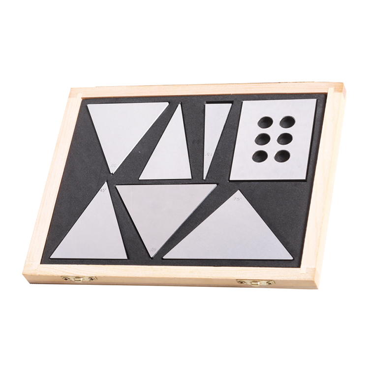 Precision 7pcs Angle Blocks Set With High Quality Type
 -
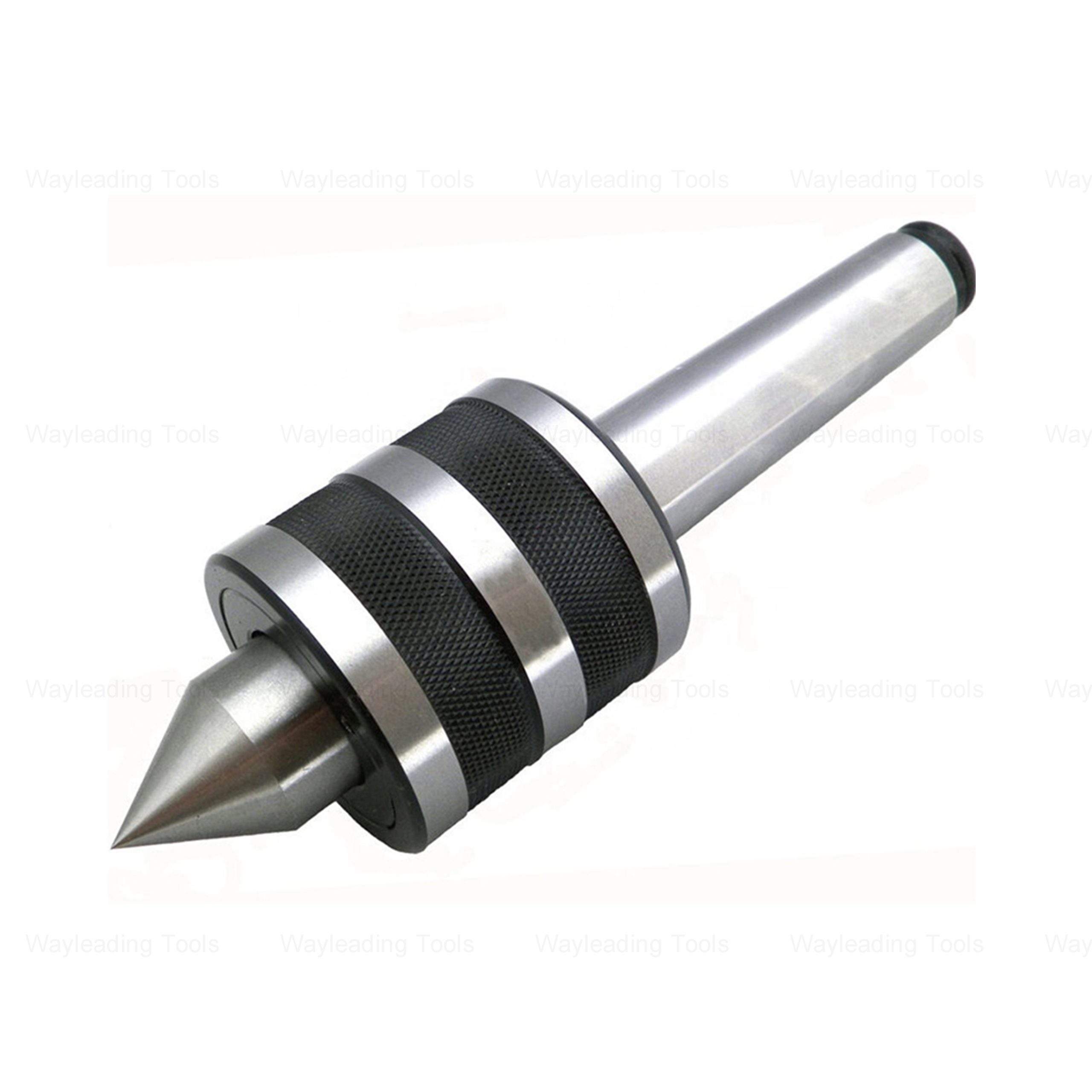 High Precision Medium-Duty Live Center – Hardened Tip, Morse Taper Shank
 -
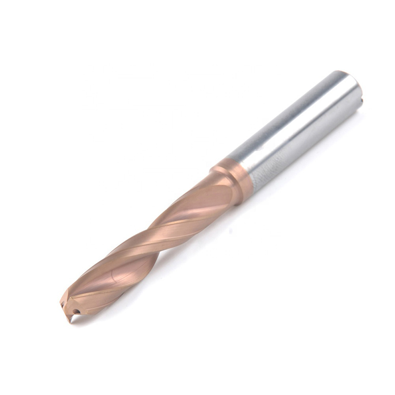
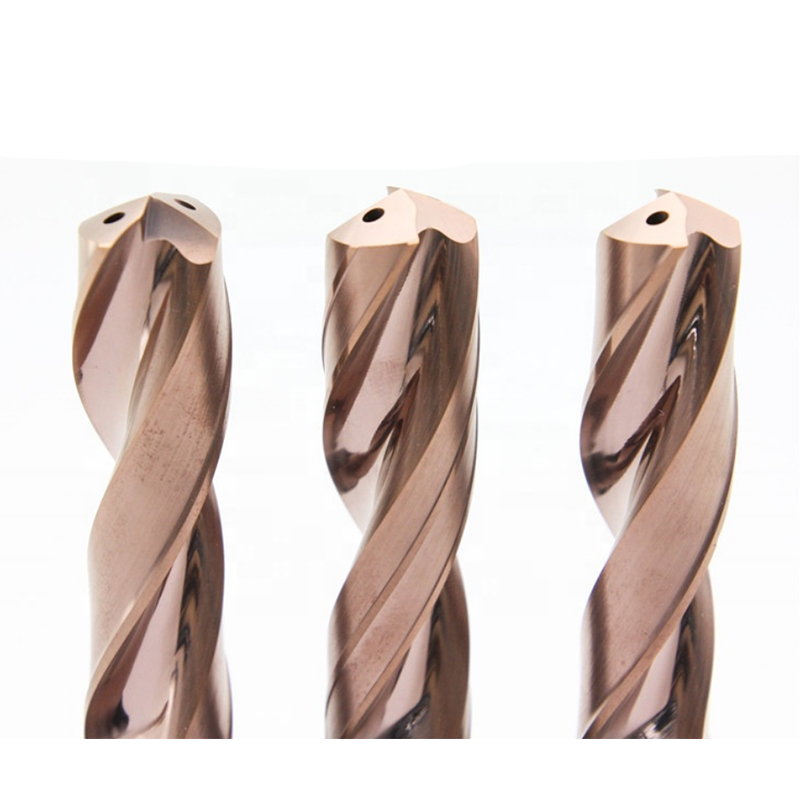 Inch Solid Carbide Twist Drill With Internal Coolant & External Coolant
 -
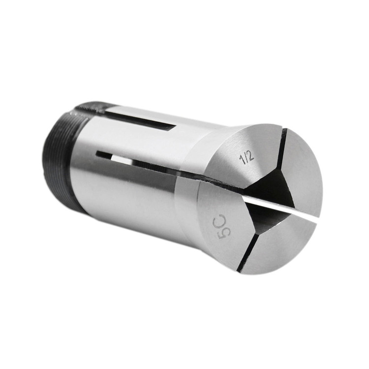 5C Square Collet With Inch and Metric Size
 -
 DIN6537L Metric Solid Carbide Twist Drill With Internal Coolant & External Coolant
 -
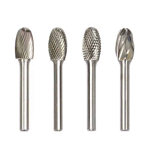 Type E Oval Tungsten Carbide Rotary Burr
 -
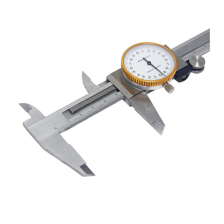 Precision Dial Caliper Of Metric & Imperial For Industrial
 -
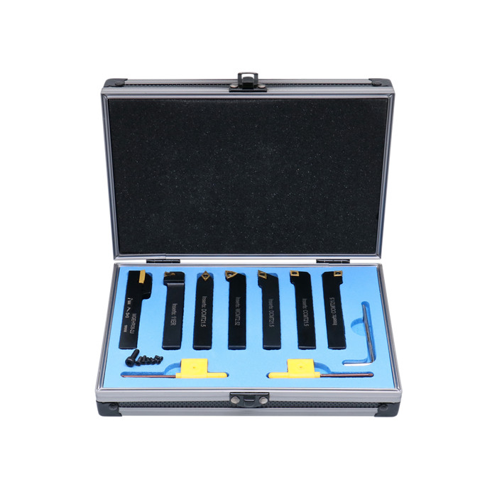 7pcs Carbide Turning Tool Set With Metric & Inch Size
 -
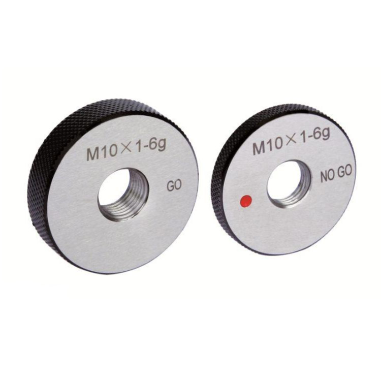 Metric Thread Ring Gauge 6g Accuracy With Go & NO Go
 -
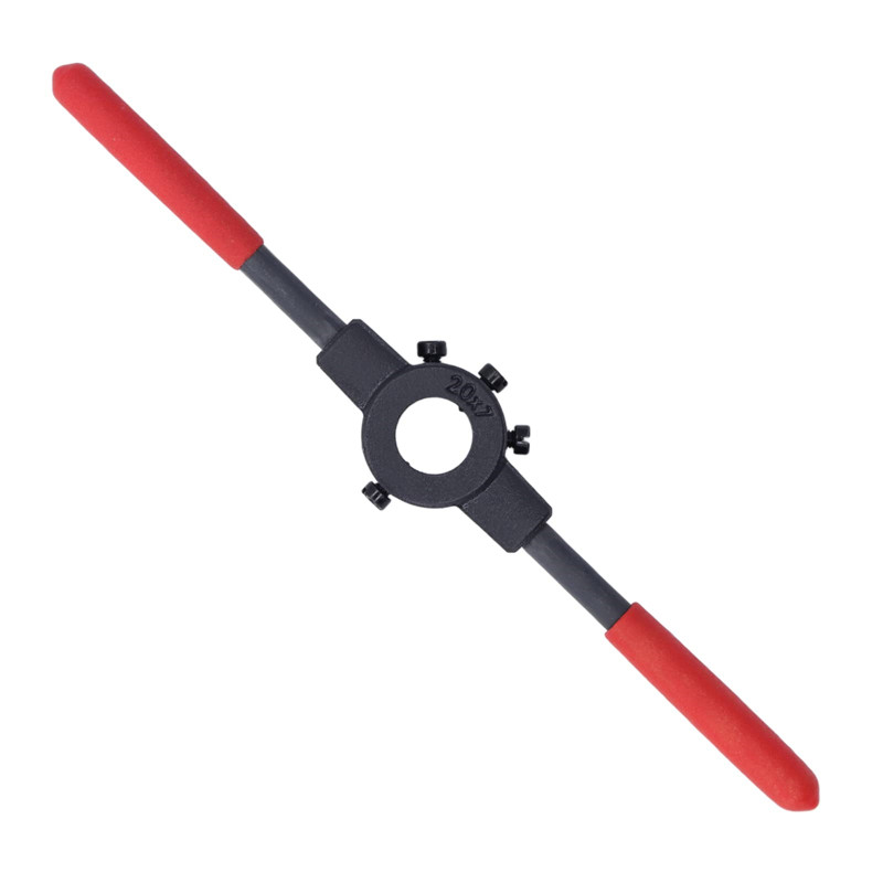 Round Die Wrench For Thread Cutting Tools
 -
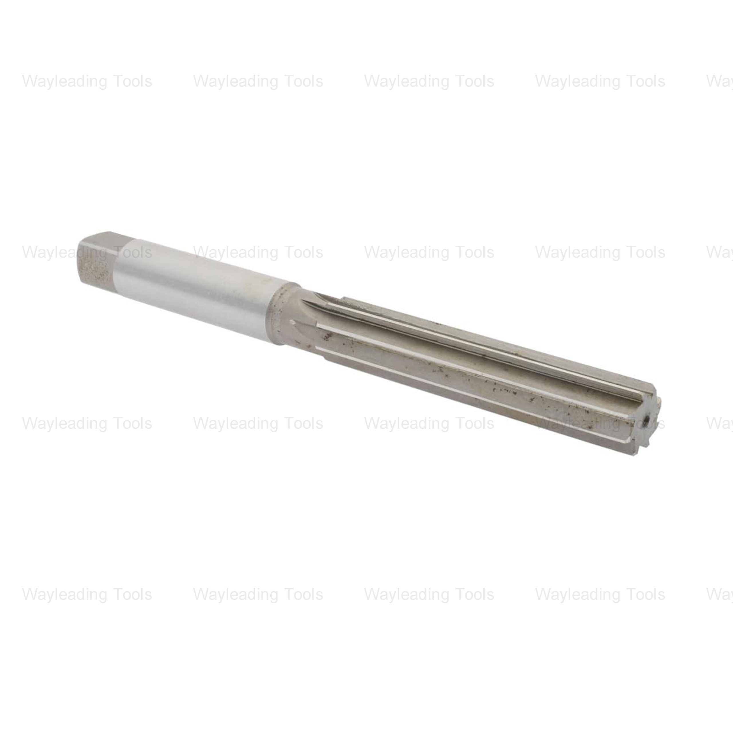 HSS Hand Reamers – Metric & Inch Sizes, Straight or Spiral Flutes
 -
 Indexable Spade Drill Holder With Helical Flute Holder And Taper Shank


