
QE parting and grooving insert Manufacturer
This article provides a detailed overview of QE parting and grooving inserts, covering their applications, materials, grades, selection criteria, and key considerations for maximizing performance. Learn how to choose the right insert for your specific machining needs and optimize your cutting parameters for efficiency and precision.
Understanding QE Parting and Grooving Inserts
QE parting and grooving inserts are essential cutting tools used in machining operations to separate a workpiece from the stock material (parting) or to create grooves of specific dimensions. They are widely used in CNC lathes and other turning machines.
What are the Key Features of QE Parting and Grooving Inserts?
Key features typically include:
- Insert Geometry: The shape and angles of the cutting edge, influencing chip formation and cutting forces.
- Insert Grade: The material composition and coating, determining wear resistance and toughness.
- Shank Size: The dimensions of the insert holder, ensuring compatibility with the machine.
- Cutting Width: The width of the cutting edge, defining the groove width or parting thickness.
Materials and Grades of QE Parting and Grooving Inserts
The material and grade of a QE parting and grooving insert significantly impact its performance and suitability for different applications. Common materials include:
- Carbide: Offers high hardness and wear resistance, ideal for machining steels, stainless steels, and cast iron.
- Cermet: Combines ceramic and metallic materials, providing excellent wear resistance and reduced cutting forces.
- High-Speed Steel (HSS): Offers good toughness and is suitable for lower cutting speeds and softer materials.
Coatings, such as Titanium Nitride (TiN), Titanium Carbonitride (TiCN), and Aluminum Oxide (Al2O3), are often applied to improve wear resistance, reduce friction, and enhance tool life. Wayleading Tools offers a wide range of coated carbide QE parting and grooving inserts designed for various materials.
Selecting the Right QE Parting and Grooving Insert
Choosing the appropriate QE parting and grooving insert involves considering several factors:
- Workpiece Material: The type of material being machined dictates the required hardness, toughness, and wear resistance of the insert.
- Machine Type: The machine's capabilities, such as spindle speed and feed rate, influence the choice of insert grade and geometry.
- Groove Dimensions: The desired groove width and depth determine the insert's cutting width and shank size.
- Cutting Conditions: Factors like cutting speed, feed rate, and depth of cut affect the insert's performance and tool life.
Step-by-Step Selection Guide
- Identify the workpiece material.
- Determine the required groove dimensions.
- Select an insert material and grade suitable for the workpiece material.
- Choose an insert geometry that promotes efficient chip evacuation.
- Select an insert holder compatible with the machine.
Optimizing Cutting Parameters for QE Parting and Grooving Inserts
Proper cutting parameters are crucial for maximizing the performance and tool life of QE parting and grooving inserts. Key parameters include:
- Cutting Speed (Vc): The speed at which the cutting edge moves relative to the workpiece.
- Feed Rate (f): The distance the insert advances per revolution of the workpiece.
- Depth of Cut (ap): The amount of material removed in a single pass.
These parameters should be adjusted based on the workpiece material, insert grade, and machine capabilities. Refer to the insert manufacturer's recommendations for optimal cutting parameters. You can find detailed specifications on the Wayleading Tools website: www.wayleading.com.
Recommended Cutting Parameters (Example - Subject to Material)
This table shows an example, actual values will vary, and should always be sourced from the insert manufacturer's specifications.
| Workpiece Material | Cutting Speed (Vc) | Feed Rate (f) | Depth of Cut (ap) |
|---|---|---|---|
| Carbon Steel | 150-250 m/min | 0.05-0.15 mm/rev | Up to insert width |
| Stainless Steel | 80-150 m/min | 0.03-0.10 mm/rev | Up to insert width |
| Aluminum | 300-500 m/min | 0.10-0.25 mm/rev | Up to insert width |
Note: These are general recommendations. Always consult the insert manufacturer's specifications for precise cutting parameters.
Troubleshooting Common Issues with QE Parting and Grooving Inserts
Even with proper selection and cutting parameters, issues can arise. Here are some common problems and potential solutions:
- Premature Wear: Could be caused by excessive cutting speed, incorrect insert grade, or insufficient coolant.
- Chipping: May result from interrupted cuts, excessive feed rate, or an unstable setup.
- Poor Surface Finish: Could be due to excessive vibration, incorrect insert geometry, or improper cutting parameters.
- Chatter: Often caused by incorrect machine setup or worn machine components.
For optimal performance, Wayleading Tools recommends regular inspection of your QE parting and grooving inserts and prompt replacement of worn or damaged inserts. Contact Wayleading Tools directly for any specialized consultations.
Conclusion
Choosing the right QE parting and grooving insert and optimizing cutting parameters are essential for achieving efficient and precise machining operations. By understanding the different materials, grades, and geometries available, and by following the guidelines outlined in this article, machining professionals can maximize the performance and tool life of their parting and grooving inserts.
Related products
Related products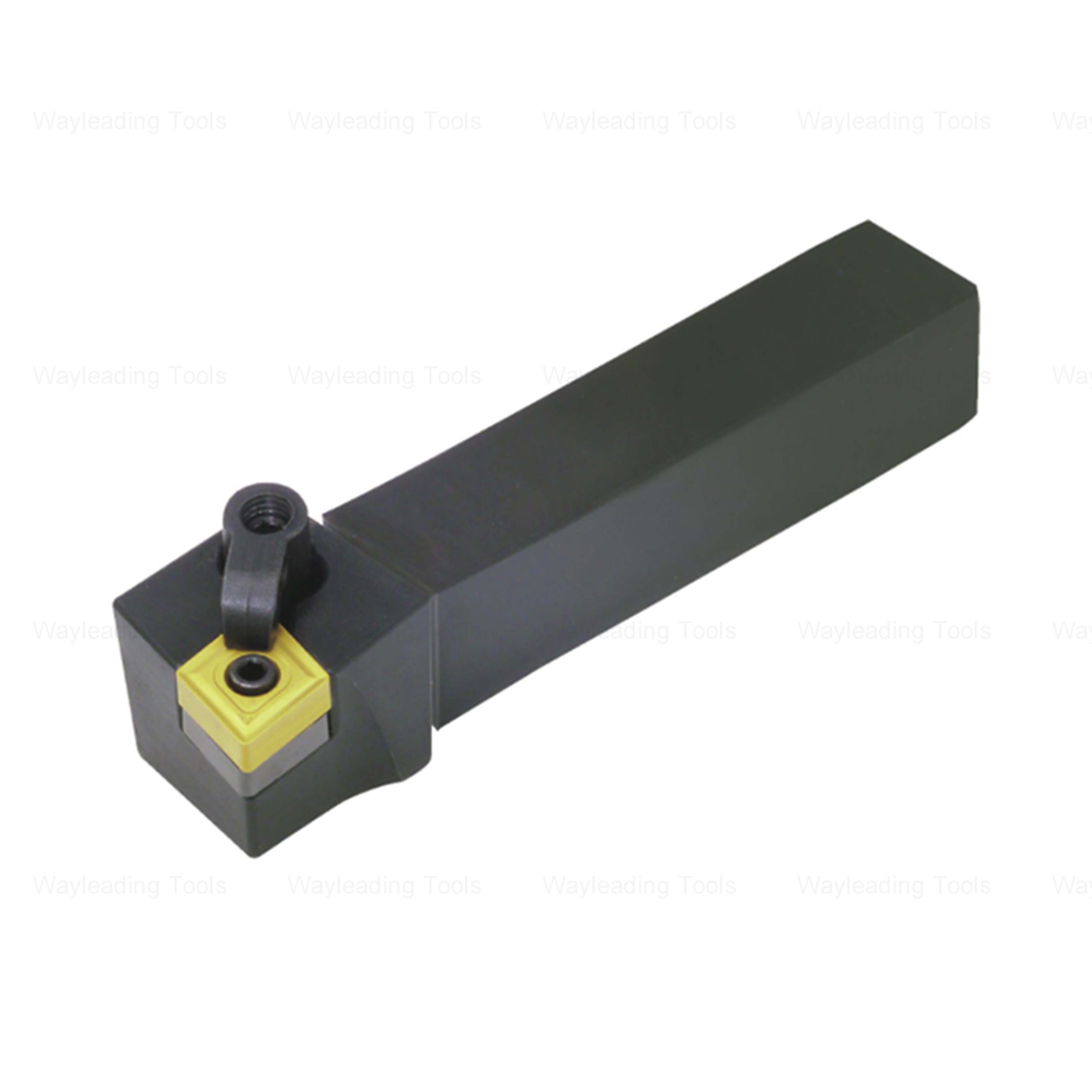
Best selling products
Best selling products-
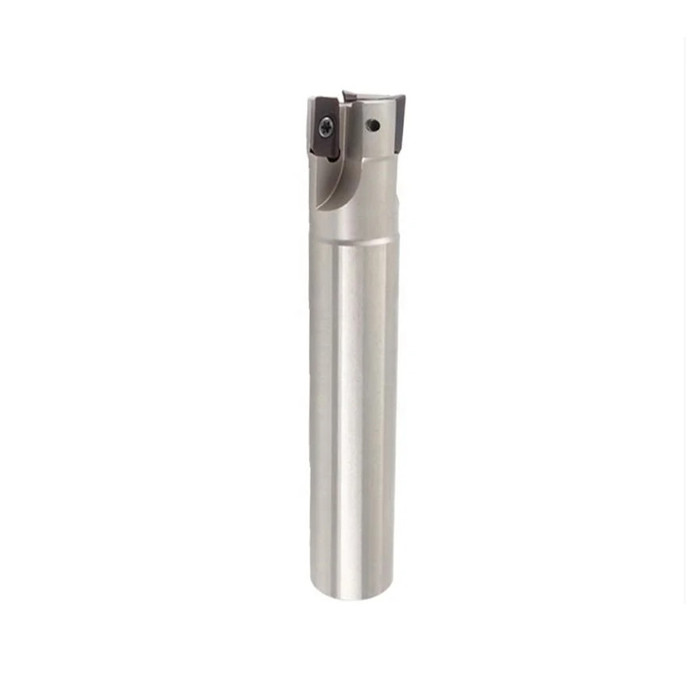 Indexable Square Shoulder End Mill For Industrial
 -
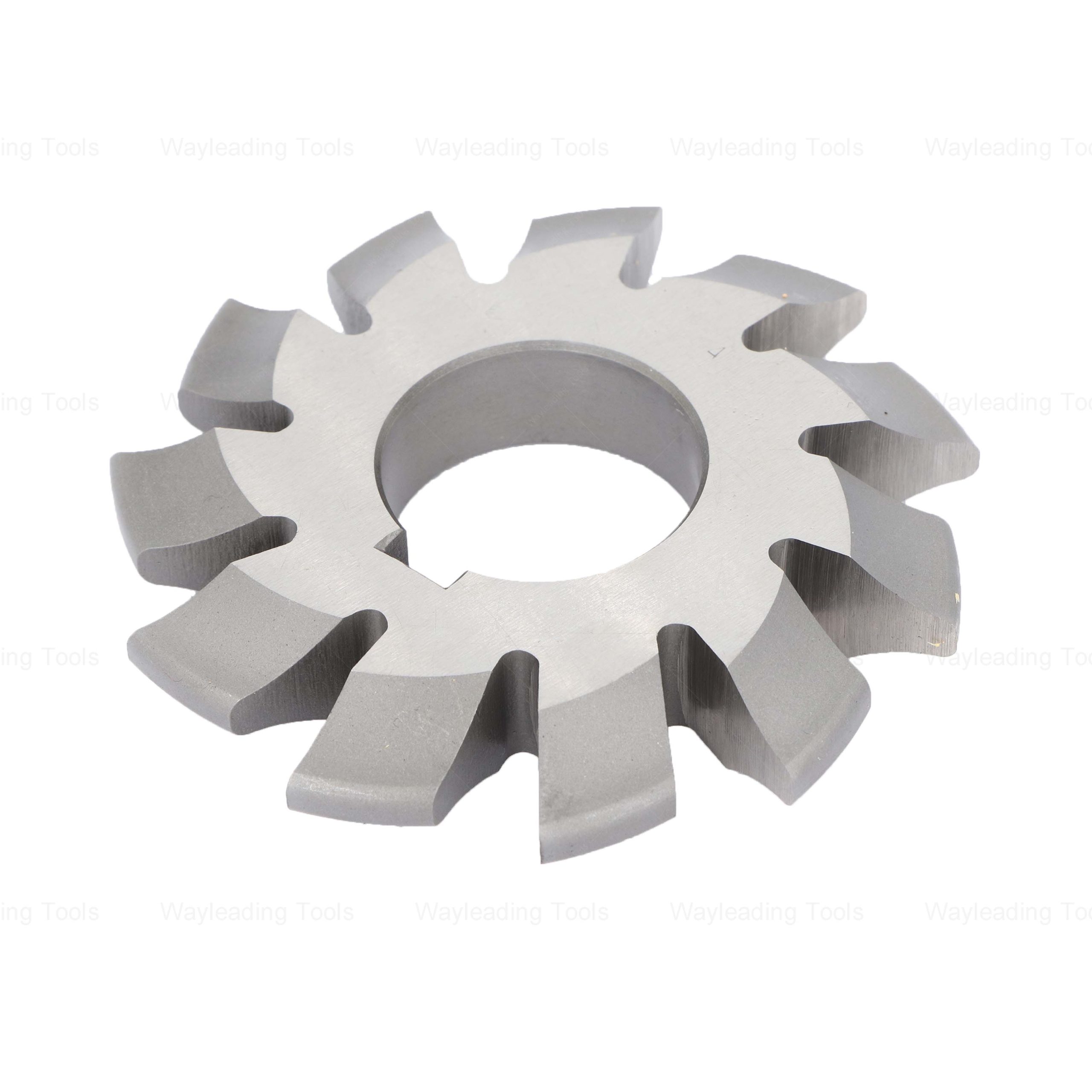 HSS Involute Gear Cutters – Module Type, PA 20° / 14.5°
 -
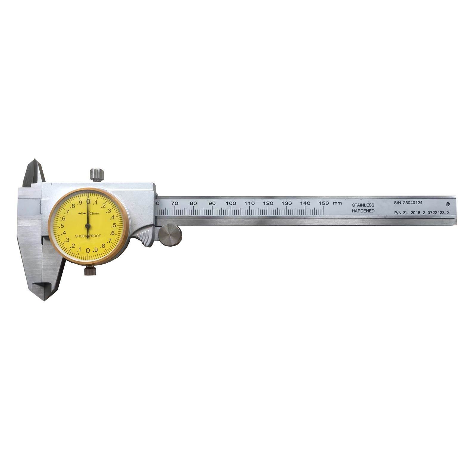 Precision Dustproof Dial Caliper Of Double Shock-Proof For Industrial
 -
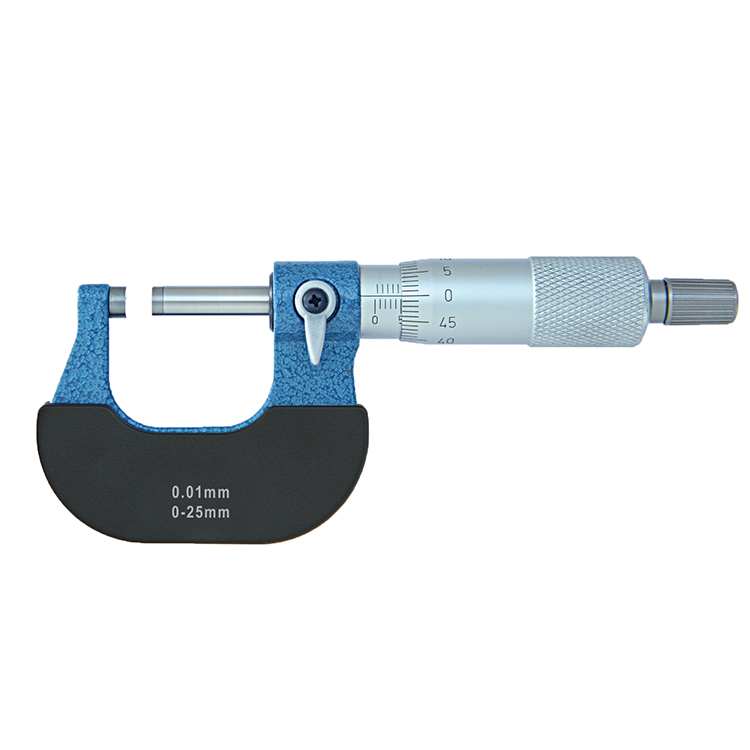 Precision Outside Micrometer Of Inch & Metric With Rachet Stop
 -
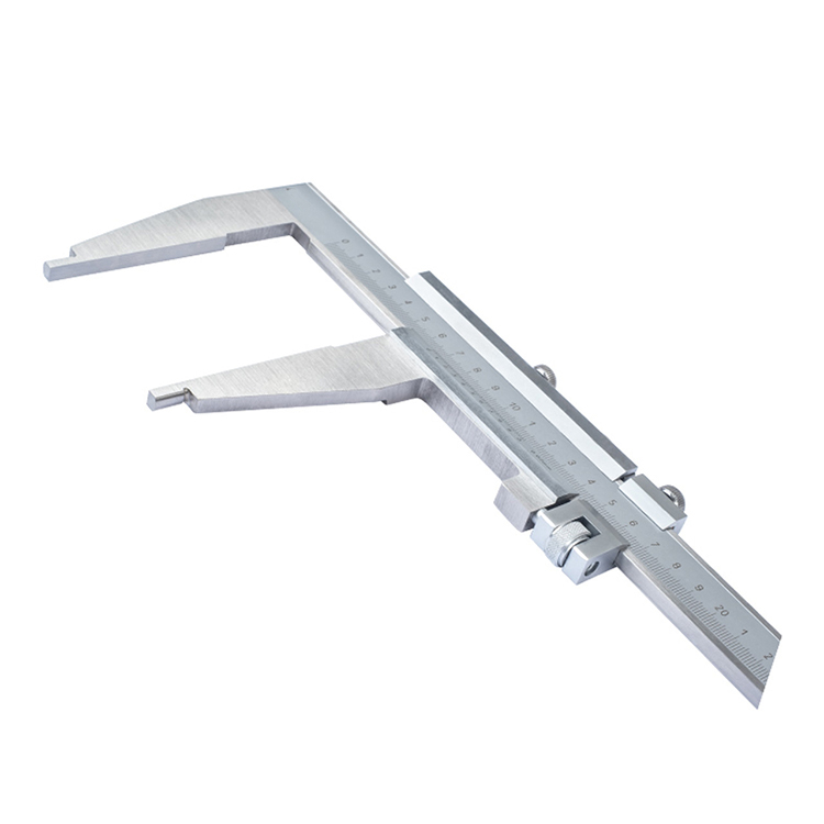 Precision Monoblock Vernier Caliper With Nib Style Jaws Of Metric & Imperial For Industrial
 -
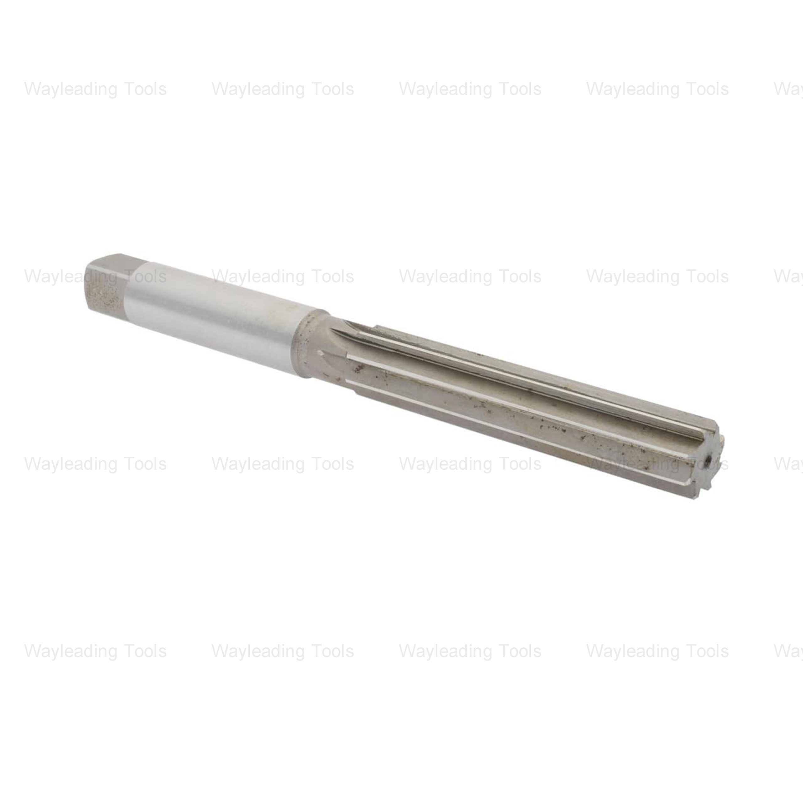 HSS Hand Reamers – Metric & Inch Sizes, Straight or Spiral Flutes
 -
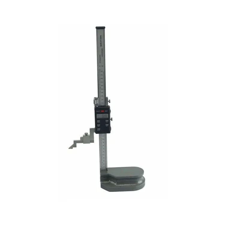 Electronic Digital Height Gauge From 300 to 2000mm
 -
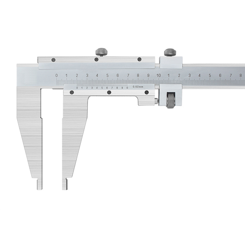 Precision Vernier Caliper With Nib Style Jaws Of Metric & Imperial For Industrial
 -
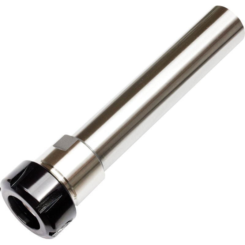
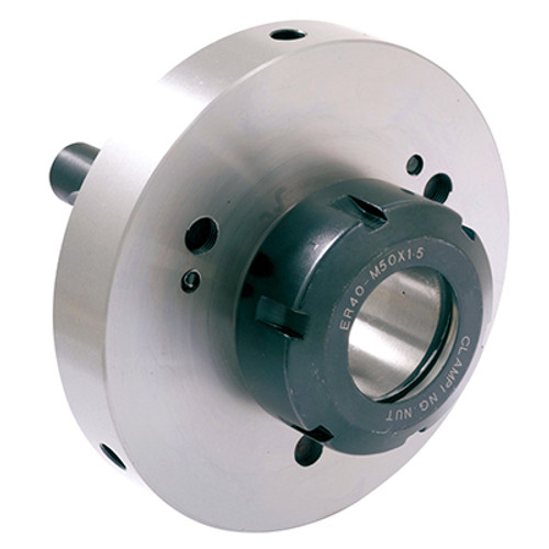 Camlock ER Collet Fixture With Lathe Collet Chuck
 -
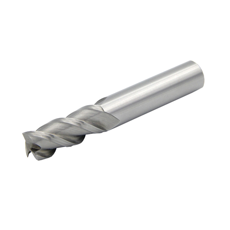 HSS Metric 4 Flute End Mills With Bright Or TiN And TiAlN Coated
 -
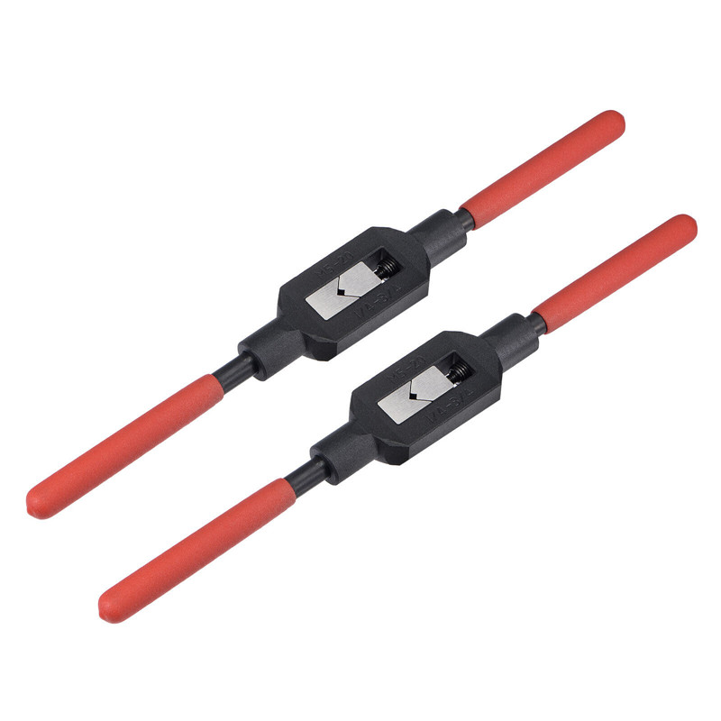 Adjustable Tap And Reamer Wrench For Thread Cutting Tools
 -
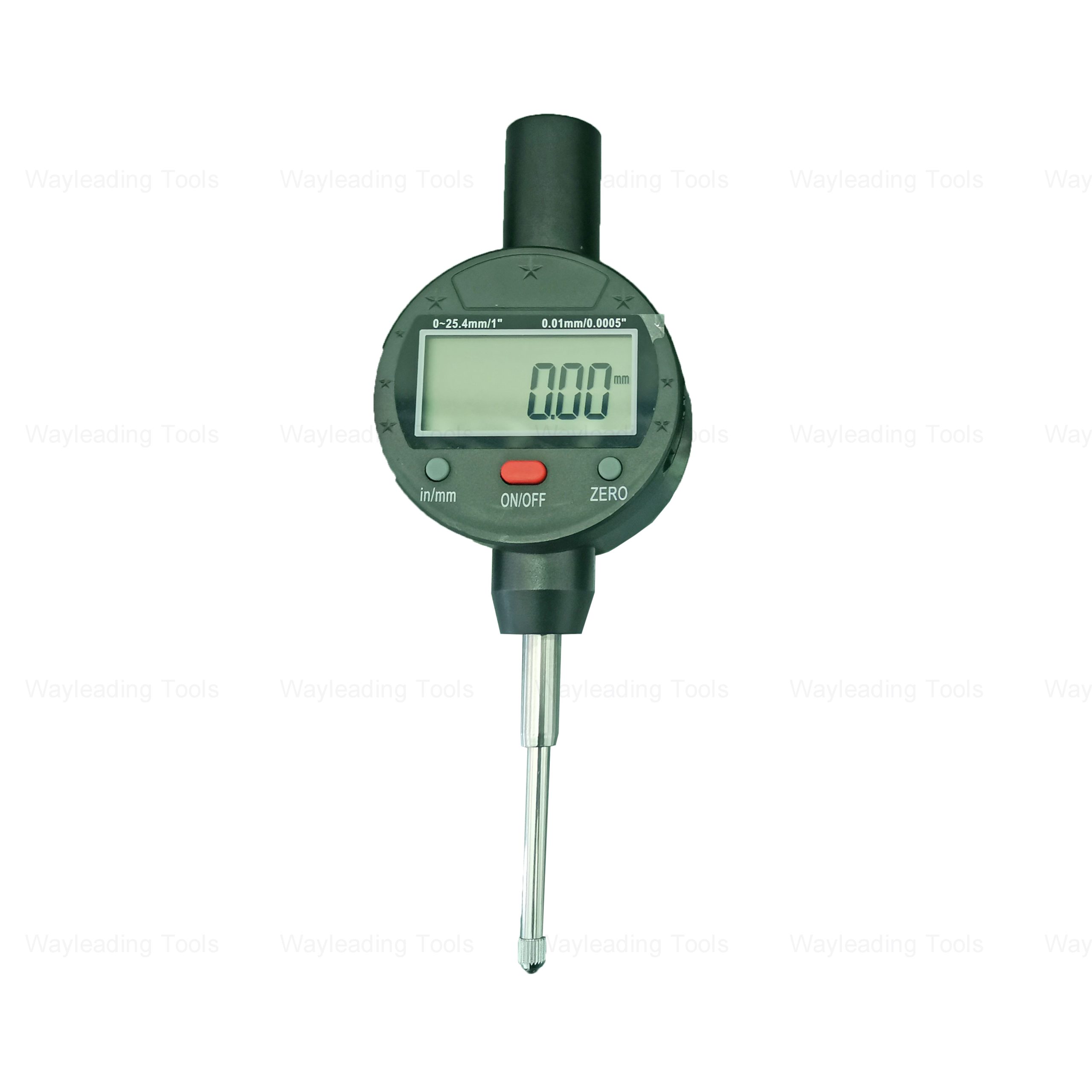 Digital Indicator – Precision Type, Inch/Metric, Industrial Grade
Related search
Related search- reduction sleeves Manufacturers
- ring gauge Factories
- High-Quality threading tool holder set
- Live center Supplier
- High-Quality vise
- face milling cutter holder Supplier
- Wholesale Stubby shank boring bar set
- carbide center drill Factories
- sn indexable thread turning tool Suppliers
- calipers with long jaws Manufacturer


